Other Parts Discussed in Thread: , AM625
Tool/software:
Team,
My customer, Eric Zuber at Collins Aerospace, has the following questions:
1) for the 2 different switching regs inside the TPS65219 PMIC, is there an equivalent discrete reg that would have more complete design tools?
Or for the PMIC is the design really just use the Cin/L/Cout values recommended and move on?
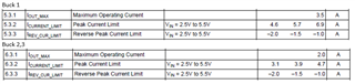
2) the datasheet indicate the I-sat of the inductor needs to be roughly 2x the rated current of the switcher…..3.5A,7.4A for #1 and 2A,5.4A for the #2/3. Is the peak current mostly set by the Iout being used – so we could reduce the I-sat spec proportionally for a design where we are using lower than the max Iout? Or is it a bit more complicated than that….just the LC switching current is rather large, even for low I-outs? Along the lines of Buck1, the switching current when operating requires a 3.9A overhead, then the actual DC load current adds to that.
did some work with ripple current estimation….is the large ripple current on this part mainly due to operation in the PFM mode? Seems to imply switch frequency could drop to ~500k in PFM – if we set in forced PWM mode, we should be able to reduce that ripple current overhead significantly?
3) it looks like TI now has a card to program PMIC EEPROM? Is that the only available method for programming, or does that use I2C such that the process could be performed in-system if desired? Is there somewhere where EEPROM contents and writes to EEPROM are documented?
Regards,
Aaron