This thread has been locked.

If you have a related question, please click the "Ask a related question" button in the top right corner. The newly created question will be automatically linked to this question.

BQ25750: SoC Gas Gauge companion part

Part Number: BQ25750
Other Parts Discussed in Thread: BQ34Z100, BQ76942, BQ25756, TPS4800-Q1

Tool/software:

Hello

We are working on a Solar Product and we are planning on using the BQ25750 for the same. However, one of the key functions that we require is a State of Charge / Coulomb counter or gas gauge function. This is not a feature on the BQ25750. Is there a companion TI part that can be used for this function? Or a recommended alternative to implement the same.

Thanks. 


  • Hello Deepakji,

    How many batteries in series are you using in your application?

    Regards,

    Adrian

  • Adrian, 

    We will be using 8S1P or 8S2P LFP battery packs for this. Also is it possible to share the design files for the BQ25750 EVM? It will help us replicate some of the power section as it is. 

  • Hello Deepakji,

    For 8S, the only gauge that will fit your application is the BQ34z100: https://www.ti.com/product/BQ34Z100

    For the design files for BQ25750 let me assign this to the charger team.

    Regards,

    Adrian

  • Hello Deepakji,

    Here are the BQ25750 design files: BQ25750EVM(2025Feb12).zip

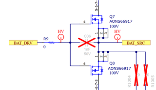
    When using an 8S battery, I recommend installing a 10Ω resistor in series with BATDRV and the BATFETs and a 10nF capacitor from BATDRV to BATSRC.

    We also have an FAQ on the BQ25750 power path that may help. We also have a general FAQ as well for the BQ2575X family.

    Let us know if you have any questions about this.

    Best Regards,
    Ethan Galloway

  • Thanks Adrian, BQ34z100 is a solution, but considering I only need a Coulomb counter function this is looking expensive for the application. I am thinking of using the BQ25750 with the BQ76942(BMS) as this will serve all purposes we need, a Charger, BMS and also a Coulomb counter - is this a viable combination? Do you foresee any potential challenges with this combination - BQ25750 + BQ76942. 

  • Thanks Ethan for the files and the recommendations, I will try to understand this and get back if I have any other questions on this. 

    When using an 8S battery, I recommend installing a 10Ω resistor in series with BATDRV and the BATFETs and a 10nF capacitor from BATDRV to BATSRC.

    You mean replace R9 on the EVM with 10Ohms and populate C36 with a 10nF cap? - I understand these will slow the turn on and off of BATFETs - why is this needed?

  • Ethan,

    In our testing today we figured out the reason for Resistor + Cap change. Without this the BATFETs were toggling probably because of the over current protection feature. 

    I have some follow-ups based on our testing today.

    1. We were not able to get the Ideal Diode mode working. Following are the conditions

    • Vin / Vac = 10V (Within the ACUV and ACOV range).
    • Battery = 25V
    •  EN_BATFET_IDEAL _DIODE  = 1
      Even in this condition the Vsys was at 10V (Vin) level. Please help understand what we are missing. My understanding/expectation is in the above case Vsys should be 25V. 

    2. We also noticed a behavior where in 

    • Vin is 36V/1A (Regulated Power Supply)
    • Vbatt is 25V , Charge current is 0.4A
    • Load is a rheostat initially drawing <0.6A
    • When we increase the load the RPSU goes into CC mode and voltage drops to 10V, charge current also drops.
    • We then decrease the load but the RPSU stays in the same CC point (10V/1A) and does not recover to 36V/1A

              Is this the expected behaviour? Why so. Conventional DC-DC regulators would recover to 36V/1A

    3. This is connected to the BATFET protection if the BATFET protection is triggered at 8A, what happens when the system load is higher than 8A. Or is the 8A limit applicable only during switchover? 

    I hope this is understandable, if not please let me know and I will try to explain in more detail. 

  • Hello Deepakji,

    1. Ideal diode mode works best when only using 1 FET. Are you using 1 or 2 FETs for ideal diode mode?

    2. I think the BQ25750 might be in Input Voltage Regulation Mode (VAC_DPM). If you make the Input Current Limit (ILIM_HIZ Current) less than 1A, the power supply should be able to recover back to 36V.

    3. The 8A limit only applies during the switchover.

    Let me know if you have any questions about this.

    Best Regards,
    Ethan Galloway

  • . Ideal diode mode works best when only using 1 FET. Are you using 1 or 2 FET

    Right now we are using the EVM, so the FETs on the EVM are as it is. 

    I think the BQ25750 might be in Input Voltage Regulation Mode (VAC_DPM). If you make the Input Current Limit (ILIM_HIZ Current) less than 1A, the power supply should be able to recover back to 36V.
    • In this case the input current will be limited to less than 1A all the time right? So this won't solve the problem as we have a PV input whose power input will vary continuously.
  • Hello Deepakji,

    Right now we are using the EVM, so the FETs on the EVM are as it is. 

    Let me look into this and get back to you.

    In this case the input current will be limited to less than 1A all the time right? So this won't solve the problem as we have a PV input whose power input will vary continuously.

    Can you enable MPPT mode? MPPT will automatically sweep across VAC_DPM settings to find the maximum power point of a solar panel or input supply.

    Best Regards,
    Ethan Galloway

  • Hi Ethan

    Let me look into this and get back to you.

    Were you able to check this?

    Can you enable MPPT mode? MPPT will automatically sweep across VAC_DPM settings to find the maximum power point of a solar panel or input supply.

    Yes we can and this is a possible solution, but this is not ideal since we will have to wait for 3 minutes and force a MPPT sweep. But more importantly I wanted to understand is this the expected behaviour from the device or are we seeing something that is not expected. 

  • Hello Deepakji,

    We recommend using 1 FET because it allows the IC to better control the FET.

    Yes we can and this is a possible solution, but this is not ideal since we will have to wait for 3 minutes and force a MPPT sweep. But more importantly I wanted to understand is this the expected behaviour from the device or are we seeing something that is not expected. 

    Yes, this is expected behavior. Can you read the status registers? The IC is probably in IIN_DPM or VAC_DPM in this mode.

    Also, keep in mind that MPPT with a 20min or 10min sweep interval would allow you to get the most power from a solar panel.

    Best Regards,
    Ethan Galloway

  • Ethan

    We recommend using 1 FET because it allows the IC to better control the FET.

    1. So this would mean the EVM cannot work in ideal diode mode? Since it has two FETs. 
    2. What changes need to be made to the EVM for the ideal diode mode to work? - which one of the two MOSFETs have to be removed for this to work? 
    3. Also what other function / feature is impacted with this change?

    We are evaluating this for a high volume application and any major or minor issues are critical for us, to ensure we don't end up getting this wrong and having many returns on our hands. 

  • Hello Deepakji,

    1. Yes, it would not work well in ideal diode mode.

    2. You would need to remove Q8 and short R1004 and R1005.

    3. If Q8 is shorted across, this would allow current to conduct from the battery to system through Q7's body diode.

    I have an alternative suggestion that may work for your circuit. Could you use a BQ25756 for the battery charger? The system load and the battery would be in parallel. Because of the MPPT mode, the solar panel voltage would not fully deplete if a high system load is applied to the BQ25756.

    Let me know if this suggestion will work. If not, could you let me tell me a bit more about the system so I can provide more suggestions?

    Best Regards,
    Ethan Galloway

  • Ethan

    I am looking at the BQ25756, it doesn't contain certain features that I was looking for, but still I could work with this. Are there any known limitations or issues similar to the BQ25750 with this part, considering they are from the same family?

  • Hello Deepakji,

    The BQ25756 is easier to work with in my opinion because it doesn't have the power path. If you still need a power path, you can use a microcontroller to control a load switch like the TPS4800-Q1.

    What all features do you need?

    Best Regards,
    Ethan Galloway