Other Parts Discussed in Thread: UC1845A
Tool/software:
Hi Folks
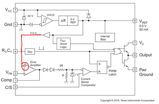
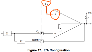
Is the Error Amplifier biased to 5V like shown in Figure 17 or is it 2.5V shown in the functional block diagram?
Best Regards
Rolf
Original question:

Tool/software:
Hi Folks
Is the Error Amplifier biased to 5V like shown in Figure 17 or is it 2.5V shown in the functional block diagram?
Best Regards
Rolf