This thread has been locked.

If you have a related question, please click the "Ask a related question" button in the top right corner. The newly created question will be automatically linked to this question.

TPS25947: Retry not 100ms

Part Number: TPS25947
Other Parts Discussed in Thread: TPS2597, TPS1663

Tool/software:

Dear support,

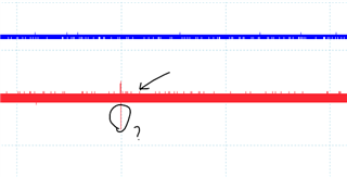
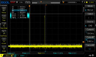
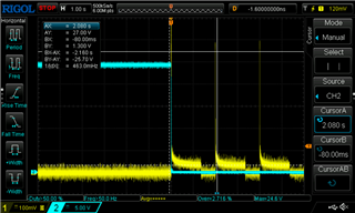
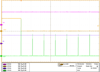
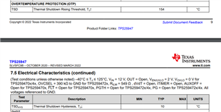
I have the circuit in two assembly variants. Both are not following the 100ms retry frequency. The output is shorted constantly. I see retry spikes every 4,5 seconds.

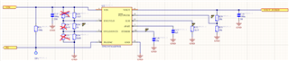
One variant shows 4,5 seconds retry:

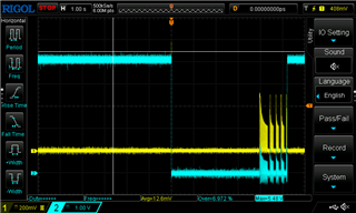
This variant shows so seldom retry, that I have no picture.

What could be the routcause?

Simon

  • Hi Simon,

    I am assuming Blue trace is Vin and Red trace is current. To verify the retry mechanism, testing wakeup in short is correct decision.

    Why is the current going negative? 

    What are these spikes and can you tell me there max value?

    Do you have any zoomed in waveform (y axis).

    Also I would recommend you to test with soft short scenario (short using resistor of small value like 0.2Ohms, etc)

    Best Regards,
    Arush 

  • Hi Arush,

    thank you for your time.

    Red is the output voltage. Due to cable inductance it gets negative on current turn off.

    The short is applied via 1m long cable, connector and banana. So it is rather soft.

    Do you have any other idea why retry time is so high?

    Should I measure the current instead of voltage?

    Simon

  • Hi Simon,

    Should I measure the current instead of voltage?

    Yes, during auto-retry, we should see some inrush current (limited to ILIM value) due to output cap or output short. Then due to higher power dissipation on device (Vin-Vout)*ILIM = (Vin-0)*ILIM, device will go into TSD and then after cooling by 10C, retry delay will start and then auto-retry.

    Red is the output voltage. Due to cable inductance it gets negative on current turn off.

    I understand but better to measure current directly.

    Best Regards,
    Arush

  • Dear Arush,

    I made a mistake with the part number. It is TPS25974. I will measure current today and come back to you.

  • Hi Arush,

    I am Simon´s colleague. I took the case for the Fuse. The part number given at the top of the thread is wrong, the correct PN is: TPS25974ARPWR

    I have made some measuremnts and the device simply doesnt try again to conduct after an over-current event:

    Ch1(yellow): voltage over a shunt (output current)
    Ch2(blue): fuse output voltage

    from my understanding the device should try every 110ms to conduct, and once overcurrent detected, then it should stop again, and this process should go on, is this correct? If so, what could cause this delay / termination of retries?


    When using the TPS16630RGE fuse, it does something like this, every 2s or so:

    Ch1(yellow): voltage drop over a shunt (output current)
    Ch2(blue): fuse output voltage 

    I assume its because of the base 1.25s delay of the thermal regulation? The problem here becomes, that this fuse, even though it retries to conduct, becomes very hot. Will the device shut down in this case due to it´s thermal regulation?

    Thanks a lot for your time and help and have a nice day.

    Cheers,
    Vlad

  • I made a mistake with the part number. It is TPS25974. I will measure current today and come back to you.

    No issue. both devices should have shown similar behavior here.

  • Hi Vlad,

    from my understanding the device should try every 110ms to conduct, and once overcurrent detected, then it should stop again, and this process should go on, is this correct?

    Yes, that is correct. Once device hits thermal shutdown threshold, it will turn off. It will wait for temperature to drop by 10C and then will start this delay of 110ms. After this it will perform retry. 

    From the waveform, it looks like the device is doing retry once and then not doing it afterwards. 

    I have this waveform from some older testing. This is TPS2597 device. I did hot-short so initial current spike is higher and then afterwards each retry will be current limited and due to high power dissipation, retries will fail.

    Is it possible for you to share the test setup and steps you are following.

    I assume its because of the base 1.25s delay of the thermal regulation? The problem here becomes, that this fuse, even though it retries to conduct, becomes very hot. Will the device shut down in this case due to it´s thermal regulation?

    What is the difference in test setup and steps followed when testing TPS1663 and TPS2597. Here the TPS1663 device looks like is doing retry. 

    Best Regards,
    Arush

  • Dear Arush,

    in your picture of TPS2597 the retries are every 100ms as expected. Can you please share the according schematic and review ours?

    Regarding TPS1663, yes there are retries, but between the retries, current is not zero. The fuse is getting extremly hot.

    Please, let's have an online meeting to discuss. We urgently need progress here, and I feel like we and you are still not even on the same page of the problem.

    Thank you,

    Simon

  • Hi Arush,

    Thanks for your quick reply.

    There is aboslutely no difference in the setup. This is how the setup looks:


    In my upper fotos, the yellow signal corresponds to the voltage measurement across the shunt and the second voltage measurement (ch2 or blue) simply for the output voltage. At the output / load there is no switch, I simply short the 2 banana connectors that I have connected to the second pin of the shunt and GND. So in this setup for both Fuses, the ICs behave differently. The TPS2597 doesnt seem to retry to conduct (according to the oscilloscope images), however after 10-20s the fuse resets and it conducts normally.

    The TPS1663 on the other hand, keeps trying and gets hot, as described before.


    FYI, for the tests, I do not hold the short circuit, I simply touch once to test the fuse and then leave open loop. 

    Thanks for your time!

    Cheers,

    Vlad

  • HI Vlad, Simon,

    Can you please share the according schematic and review ours?

    I used TI EVM. The schematic is present in the user guide document. https://www.ti.com/lit/ug/slvucc0a/slvucc0a.pdf?ts=1739333062751&ref_url=https%253A%252F%252Fwww.google.com%252F 

    This test which I showed is hot-short and then keep holding the short. Your schematic also looks fine. Anyways, the BOM won't affect the auto-retry mechanism of this device.

    Please, let's have an online meeting to discuss.

    We can have a quick sync up if it is required.

    I will suggest few things. Please let me know if they help.

    • Try with external EN signal (give 2V at EN pin). GND the OVLO pin. I am just telling these things to isolate this issue.  
    • Keep holding the short at output. See if device starts doing retries. Redo this with soft short (0.1 or 0.2Ohms resistor)
    • Is this repeating with multiple devices or boards. 
    • Do you have TI EVM?

    Best Regards,
    Arush

  • Hi Arush,

    I did as you suggested: En to external 2V, OVLO to GND and a SC yielded this:


    Holding the short and removing yields this:


    The setup remains the same: 

    Ch1 (yellow) voltage drop across the shunt (0.1Ohm)
    Ch2 (blue) output voltage of the fuse

    For both tests 0.1 Ohm shunt was used. While keeping the short, the same result can be seen as by the TPS1663, the fuse retries, but just gets really hot. Is it safe to assume that the thermal protection will stop the device from trying until the temeprature is safe again?

    So the 2V at EN and OVLO to GND seems to do the trick. With this test you wanted to isolate the issue. What is your opinion on this, what do you think the issue is? Does the device see an overvoltage at input during a short and hence stops trying to conduct? If so why wouldnt it try at all, later, like 2 or 3s after the initial short, since the input voltage would have became stable again in this time, or am I missing something?

    Yes, this was repeated with 2 same TPS2597  Fuses, but I only tested 1 with this new configuration / test from you. 

    Thanks for your time and cheers,

    Vlad

  • Hi Vlad,

    Holding the short and removing yields this:

    This looks good. We can see auto-retries. 

    but just gets really hot. Is it safe to assume that the thermal protection will stop the device from trying until the temeprature is safe again?

    Yes, Thermal protection will trigger when junction temperature reaches 154C (typical) and will wait for device to cool down by 10C i.e. 144C and then it will start the retry delay timer of 110ms. So during continuous TSD events, your average temperature of device will be very high. TSD prevents immediate damage to device but this high operating temperature is not allowed for the device. The good part here is, we don't expect device to operate like this during normal operation and we only expect this kind of behavior during some faulty state.

    What is your opinion on this, what do you think the issue is? Does the device see an overvoltage at input during a short and hence stops trying to conduct? If so why wouldnt it try at all, later, like 2 or 3s after the initial short, since the input voltage would have became stable again in this time, or am I missing something?

    I wanted to remove possibility of UVP or OVP hitting when doing the test hence I requested this setup. Most likely Vin was dropping to low value and hitting UVLO or UVP which resets the device. Then the device will perform startup. Honestly, I would expect the device to show retries even if this was the case. To further root cause this I would suggest capturing some waveform with older setup. Probing EN and OVLO pins might give us some insights. 

    Another thing that is possible is negative voltage at output when doing the short. Soft short will reduce the negative voltage. In your schematic, there is no output transient protection and cap is also very less, so negative output voltage during short circuit might have reset the device (violating the abs min limit of device).

    Best Regards,
    Arush

  • Hi Arush,

    Thanks a lot for your reply and thanks for the explanation. 

    We have another TPS2597 fuse that is connected to a 12V power rail. We´ve been having some problems with both of them (5V and 12V). In the previous message, the measurements are from the 5V and here, we´ve adjusted the UVLO and OVLO voltages and retested and now with new thresholds it seems to work fine:

    As long as the short is held, the circuit retries, when short is removed, the fuse conducts.

    This however is not the case for the 12V Fuse, the second TPS2597, here I have also done what you suggested, set the UVLO to 6V with an external power supply and the OVLO to GND. The device retries to reconnect but it does it each 2s or so. This also worked with floating EN/UVLO, however here the frequency was smaller:

    No EN/ UVLO voltage (floating):


    With 6V on EN/UVLO:


    Even if the input voltage would drop for a very short time, this should still not hinder the device to try to reconnect more often, some time after the Vin was back inbetween the safe operating limits, correct? Any ideas why the device is retrying this slow? And is it supposed to do it with En / UVLO floating?

    How could we arrange a call? 

    Thanks for your time and have a nice day / evening.

    Vlad

  • Hi Vlad,

    Even if the input voltage would drop for a very short time, this should still not hinder the device to try to reconnect more often, some time after the Vin was back inbetween the safe operating limits, correct? Any ideas why the device is retrying this slow? And is it supposed to do it with En / UVLO floating?

    Device retry is not dependent on the EN UVLO or OVLO. I only asked you to do that since sometimes during high current test, wire drop triggers these fault states preventing retry. 

    Can you help me in understanding the differences between both these rails. Any BOM difference?

    Best Regards,
    Arush

  • Hi Arush,

    Sure, the only difference between the rails is that one is 12V and the other one 5V. For both of them the current limit is set to 5A on the Fuses. By adjusting the UVLO and OVLO we got the 5V fuse (TPS2597) to work properly just like the other bigger fuse we use for 24V (TPS1663 - this worked from the beginning, was just getting hot), that is why I asked about the influence of the UVLO and OVLO voltage on the retries, since when in fault state, there are no retries. 

    The BOM difference between the 12V and 5V fuses, are the resistors setting the UVLO and OVLO. 
    The 12V Fuse circuit:

    And the 5V Fuse circuit:

    Despite that, as you can see, everything is the same in the circuit. 

    Thanks for your time and have a nice day/ evening.

    Cheers;

    Vlad

  • Hi Vlad,

    This is unexpected. As previously mentioned, UVLO and OVLO don't directly influence the retry time delay. I asked to use external supply since during high current event, wire drop can result in them tripping which will prevent retry from happening until the OVP or UVP state is removed. This should anyways clear in the test case (short circuit) but still wanted to remove these variables hence I asked you to do this.

    I would recommend to replace the device to check if this is following the device and would also recommend evaluating the device on TI EVM.

    Vlad, please accept my friend request on e2e. 

    Best Regards,
    Arush