This thread has been locked.

If you have a related question, please click the "Ask a related question" button in the top right corner. The newly created question will be automatically linked to this question.

LM5176: Stop and Restart at the EN/UVLO Pin During Boost Operation

Part Number: LM5176

Tool/software:

I have a question regarding the operation of the boost converter.

After stopping the operation by setting the EN pin from high (5V) to low, and then setting it back to high, the HDRV2 stays high for several tens of milliseconds.

When the output is unloaded, the output voltage is maintained by the output capacitor, so during this high period, a large current flows to the input side.

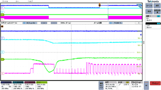
I will upload the measured waveform. This waveform shows the behavior when boosting from a 15V input to a 36V output.

Ch1: EN/UVLO, Ch2: Output voltage, Ch3: inductor current, Ch4: HDRV2

Is it normal for HDRV2 to stay high for several tens of milliseconds when EN/UVLO goes high?

  • Hi Tetsuya,

    thank you for using the E2E forum.

    The mapping of the channel in the scope plot seems to be wrong. It think it should be

    Ch1: EN/UVLO, Ch2: Output voltage, Ch4: inductor current, Ch3: HDRV2

    Can you also probe the SS - e.g. instead of the inductor current.

    Best regards,

     Stefan

  • Hi Stefan,

    Thank you for the response.

    As you mentioned, Ch4 is the inductor current and Ch3 is HDRV2.
    Also, the time when HDRV2 is on is not several tens of milliseconds, but approximately 70 microseconds.

    I have measured the waveform of the SS terminal.

    Ch1: EN/UVLO, Ch2: Output voltage, Ch3: HDRV2, Ch4: SS terminal

    Best regards,

  • Hi Tetsuya,

    the controller is executing the startup phase where it tries to ramp up the output voltage slowly with the ramp of SS. In this mode and time the controller does only work in DCM mode and prefvnting to discharge the output cap. As the output cap is still charged, the controller does not start operation of the power stage but the regulation loop is keeping the COMP voltage low. 

    Now when SS has reached the level of VREF the controller starts operation also in CCM mode but COMP is still not settled to the required value. Therefore you see this short reverse pulse in the inductor current and the longer HDRV2 pulse.

    Best regards,

     Stefan