This thread has been locked.

If you have a related question, please click the "Ask a related question" button in the top right corner. The newly created question will be automatically linked to this question.

LM27761: LM27761 output abnormality, severe chip heating

Part Number: LM27761

Tool/software:

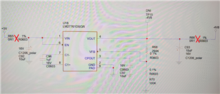
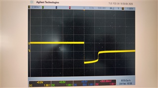
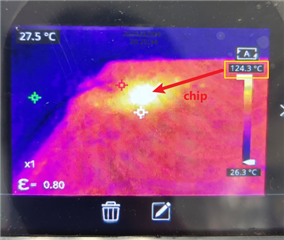
I want to use LM27761 to convert from+5V to -4.8V. The output waveform (TP15) shows that the output voltage drops by about half after power on, and the temperature of the thermal imaging display chip rises rapidly. If the chip is continuously powered on, it may be burned out. During testing, R65 and R66 were removed to eliminate interference from other circuits. What is the problem? How can I improve this design?

  • Hi Zac,

    The IC temperature seems to indicate the IC is damaged. Did you try with a different IC? While turning on VIN try making sure it doesn't overshoot the ABS max rating of 5.8V. You can try ramping it up from 0V slowly.

    You can experiment by replacing the polarized caps with ceramic non polarized ones. Can you also take a scope shot of VIN, CPOUT, C1+ during startup for a new IC?

    Best regards,

    Varun

  • Hi Varun,

    When I replace C92,C93 with MLCC capacitor, the output return to normal, at the same time, I notice that the manual has a description recommending the use of MLCC capacitors. the result proved that it was indeed the influence of this. thank you very much.

    But for a deeper analysis, how should it study the effect of capacitor ESR on this circuit? Could you provide some ideas? Thank you.

  • Hi Zac,

    I see 2 possibilities on why this could have happened.

    1. The ESR of C93 can affect the control loop gain. A higher ESR can also cause more output noise which may have caused a misbehavior of the device.
    2. The polarized tantalum cap is somehow damaged and has a higher leakage.

    Best regards,

    Varun