


Other Parts Discussed in Thread: BOOST-PSEMTHR8-097, TPS2373-4EVM-758, , TPS23881B, TPS23881, BOOST-PSEMTHR-007
Tool/software:
Hi I am a long time user of TI products and first time posting a question to the forum.
Let me list out my setup:
I have BOOST-PSEMTHR8-097 w/ TPS23881B1EVM-24, the jumpers on the board are setup for 2P-30W and I have the TPS2388x GUI running and I have setup the ports as auto mode and have applied 56V to the EVM. I also have a TPS2373-4EVM-758 as a "known good" board that I am using to confirm that the evaluation board is working correctly. I also have my own custom PCB that I am trying to test and get working with POE.
1. I have fully tested that the onboard non-isolated DCDC is working perfectly, I cut the trace after the TPS2372 to confirm that the DCDC is fully working and the problem is not within the power stage of the circuits that I have designed.
2. The board seems to be fully getting through the detection, class, and mark POE detection, but for some reason the chip fails to "connect" the VSS to the Return and connect the path to my DCDC converter.
Troubleshooting steps:
- Removed all ancillary components in the POE path so that it is basically just the full bridge rectifiers and the components required for the TPS2372 + a 0.1uF 100V cap
- Components removed are a shunt resistor - replaced with a 0 ohm jumper (10mohm), ferrite beads - replaced with a jumper on VDD/VSS and several other filter capacitors. The placement of those components don't seem to cause any problems.
- Verified DEN = 24.9k, CLSA = 63.4ohm, CLSB = 90.4ohm, Autoclass connected to VSS and Open (makes no difference, but I did confirm that the TPS23881B does "see" that it is requesting autoclass), I am leaving IRSHDL_EN, MPS_DUTY, AMPS_CTL all open and not connected to anything
- Verified that REF is 49.9k and I have hooked scope up to pin and it does generate 1.5V and does turn on
- the TPS23881 is detecting that the channel is connected, R is valid, it sees that the board is requesting class 8, but reports the following error via the GUI:
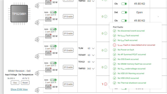
- This seems very confusing to me as it seems to be fully detecting the POE, but failing to actually do the last step and apply the load to the port.
- Here is my scope image:
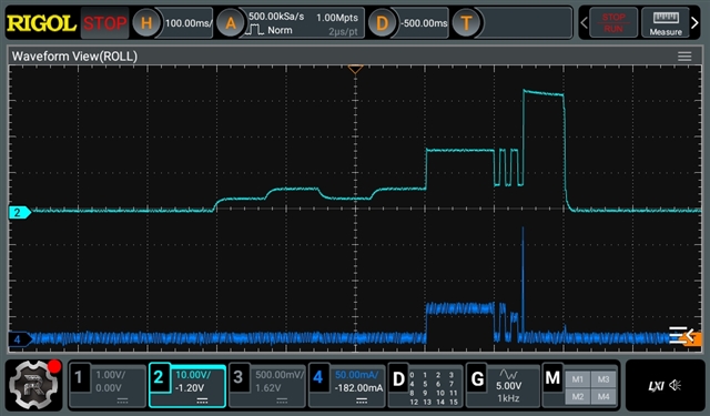
CH2 = voltage 10v/div, CH4 = current using 25Mhz AC/DC probe in 50ma/div
To my untrained eye this looks good or like the first part of the communication is working perfectly, but for some reason the voltage does not go up to the ~50V instead it goes up to like 33V. Which my understanding is basically telling the POE PD to disconnect rather than connect.
Any help is extremely appreciated!!!
- Thanks Jake
