This thread has been locked.

If you have a related question, please click the "Ask a related question" button in the top right corner. The newly created question will be automatically linked to this question.

TPS1663: TPS16630 short Circuit

Part Number:  TPS16630

Tool/software:

Hi team,

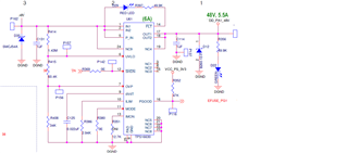
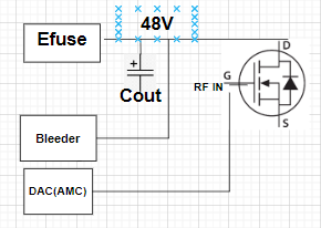
We are using an eFuse on the GaN RF amplifier's drain supply rail and encountering an issue where, upon enabling RF power,  the eFuse sometimes gets damaged. Sometimes, the fault LED blinks, while other times, the DC-DC converter itself fails. In this situation, the RF section was not found to be short. Why is the short-circuit protection not functioning reliably? 

The Vin Voltage 48V

GaN max current 1.5A.(controlled bias sequencing)

input supply isolated Dc-DC 48V /26A with LC filter.

ILim= 6A

  • Hello Anoop,

    Welcome to E2E.

    Can you help with waveforms ?

    Please get VIN, VOUT, FLT and IIN if possible.

    What's the inrush current and load during start-up?

    Thanks 

    Amrit 

  •  Hi Amrit

    Thanks for the reply.

    We don't have waveforms because this is an 8-channel system, making it difficult to determine which channel is causing the issue, especially since the problem does not always occur.

    The sequence is as follows:

    1. The 48V e-fuse is enabled for all 8 drain channels.
    2. After that, the gate voltage is set.
    3. Only then is RF power enabled.

    Additionally, the drain pin is connected to two 470µF capacitors.

    Inrush current  400mA 

    Thanks,

    Anoop

  • Hello Anoop,

    Is there negative voltage induced on the device?

    Can you send me your GaN RF schematic which is connected to TPS2663 output?

    If you want, we can have this discussion online and further debug step.

    Thanks 

    Amrit 

  • Hi Amrit,

    Is there negative voltage induced on the device? ->I haven't tested it

    The GaN connected to the eFuse is the GTRB384608FC

    We shorted the eFuse output with a 4A resistive load during testing, and it successfully provided protection.

  • Hi Amrit,

    Is there negative voltage induced on the device? ->I haven't tested it,but I will check

    The GaN connected to the eFuse is the GTRB384608FC

    We shorted the eFuse output with a 4A resistive load during testing, and it successfully provided protection.

  • Hello Anoop,

    Thanks for sharing the block diagram.

    Can you help me understand the test case in detail. Do you start-up issue? How do you come to conclusion that eFuse is damaged?

    During short circuit test, GaN FET is OFF or ON? or is it in transition?

    Do you use negative voltage to turn off the GaN FET?

    Thanks

    Amrit 

  • Hello Amrit,

    Do you start-up issue, 

    How do you come to the conclusion that eFuse is damaged?:- >EFuse input and output showing low resistance, Discreet part all are fine

    During the short circuit test, GaN FET is OFF or ON? or is it in transition? ->We test with Resistive load. GaN is not used.

    Do you use negative voltage to turn off the GaN FET?-> GaN pinch of voltage is  -ve 6V

    Thanks,

    Anoop

  • Hello Anoop,

    It would be easy to investigate with wave forms.

    Please check if you can capture waveforms as mentioned previously. 

    About the down stream load, you mentioned there are DC-DC converters.

    Are you using power good pin to enable?

    What’s the total output cap including down stream caps?

    Thanks 

    Amrit 

  • Hellow Amrit,

    Please check the captures below

    Experimenting with the MAIN PA eFuse: -> Monitored the input voltage along with the input current of the eFuse (Cdvdt= 0.022uF) on DSO.

    1) Efuse - ON Gate-> OFF.  (Drain capacitor 660uF)


    -> eFuse Input current
    Large blue circle -> eFuse Input voltage
    Red circle -> eFuse Output voltage

    2) TX ON  (E-fuse ON, GaN ON)
    Here the IDQ current is changed for Carrier ( varied +/- 800mA) a) IDQ current changed to -2.80 

    3) PA - OFF(Gate off, Efuse Off)


    -> eFuse Input voltage
    Large blue circle -> eFuse Output voltage -->>

    Short circuit experiment Wtih Resistive load

    4)

    Monitoring the eFuse I/P and FLT pin of eFuse:

    * To check the fluctuations at the eFuse input and the eFuse FLT pin when short circuits at the output side with load 2A.(resistive load)

    5)

    Monitoring the eFuse I/P and FLT pin of eFuse:

    * To check the fluctuations at the eFuse input and the eFuse FLT pin when short circuits at the output side with load 4A.(resistive load)

    Thanks,

    Anoop

  • Hello Anoop,

    I will analyse these waveforms and get to you by tomorrow EoD.

    Thanks 

    Amrit 

  • Hi Amrit,

    Any update?

    Thanks,

    Anoop

  • Hello Anoop,
    Sorry for the delay here.

    What's the current level during short circuit? let me know if you have measured.

    From FLT pin, it looks like some other fault happened before short circuit as device is not latch off.

    Can you include input current and output voltage in same waveform?

    On first waveform on inrush current. Do you have load resistance connected during start-up?

    It looks like going into thermal regulation.

    Thanks 

    Amrit 

  • Hi Amrit,

    Can you include input current and output voltage in the same waveform?-

    C2 Output Voltage,C1 Input current

    On the first waveform on inrush current. Do you have load resistance connected during start-up? , No, Only 660uF capacitive load.

    From the FLT pin, it looks like some other fault happened before the short circuit as the device is not latched off.- we don't have

    Thanks,

    Anoop

  • Hello Anoop,

    Can we have online meeting to discuss?

    Let's connect on email to discuss this.

    Can you share your mail id?

  • Hello Amrit,

    sorry for delay i sent friend request

  • Continuing on mail.

    closing thread here