This thread has been locked.

If you have a related question, please click the "Ask a related question" button in the top right corner. The newly created question will be automatically linked to this question.

TPS61023: Unable to withstand for Output current of 200mA

Part Number: TPS61023
Other Parts Discussed in Thread: TPS2553, TPS61252, TPS61033, TPS61253

Tool/software:

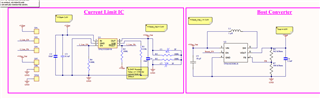
I'm working on a new design (for an alternative circuit for LTC3125) that will operate with a 3.6V battery as input as in the circuit given below

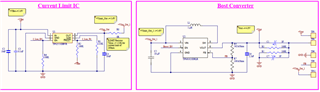
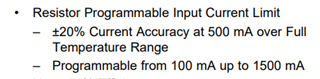
So here I'm expecting the battery shall be able to charge the 2 supercapacitors (C1 & C7) within 30 Seconds up to 4.0V (as configured using TPS61023 R4 & R7 resistors) & this shall be done using a current limiting IC TPS2553 which will limit the Input current to 200mA from 3.6V Battery.

But when i turn ON the circuit, At the output of Current Limit IC(+Vlim_Out) the voltage is dropping up to 1.9V on average & average input current across R8 is 162mA initially (Attached image-2), 
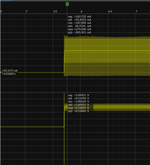
                Image-2

When image-2 zoom in to much deeper for as attached below image-3, i can see a high & low current peaks.
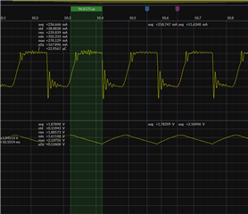
                        Image-3

Although this circuit is able to charge the super capacitors with in 80 seconds, but when Vout is connected to a GSM Modem (IoT Modem), then Vout is not able to withstand on the 4.0V charged voltage.

But when TS2553 tested individually on full load it is able to provide 200mA with a voltage drop of Battery from 3.6V to 3.3V (Attached Image-4), but when Current Limit IC(+Vlim_Out) was connected to boost converter, then its not working.
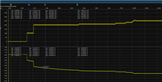

                                 Image-4

Please let me know the solution for my issue. Thanks in advance

  • Hi Prasad,

    If you need lower current limit on VBAT side, please choose a boost converter with lower current limit like TPS612995. 

    Best Regards,

    Travis

  • Hi Travis,

    Thanks for your suggestion, but TPS612995 part is not readily available in the market & in the TI site also.

    Do i have any alternative solution for this to limit exactly 200mA of current at input.

  • Hi Prasad,

    Please look at TPS61252. The current limit can be configured by an external resistor

    Best Regards,

    Travis

  • Thank you Travis

  • Hi Travis,

    With the TPS61252 IC it will allow input current of 200mA but supports output only up to 0.5A Nominal (As per WEBENCH settings), but I need the output with 2.0A, 3.0A pulse load for a IoT Modem consumption.

     Will this IC supports that application. Please let me know

  • Hi Prasad,

    Forgive me if I didn't understand your application correctly. Your output should be super capacitor and the pulse load should be supported by the energy of the capacitor. 

    Best Regards,

    Travis

  • HI Travis,

    We are using an IoT modem that requires 4.0V with a 2.0A pulse load. For this application we are looking for a new IC that can limit a 3.6V battery's input current to 200mA while boosting the output to 4.0V to charge the supercapacitors, which will support the pulse load consumption.

    Can you recommend a suitable alternative for this application? We are currently using the LTC3125, but it is quite expensive.

  • Hi Prasad,

    TPS61252 can limit a 3.6V battery's input current to 200mA while boosting the output to 4.0V to charge the supercapacitors. And supercapacitors will handle the pulse load.

    Best Regards,

    Travis

  • Hi Travis, 

    I wanted to know why my first circuit "combination of TPS2553 with TPS61023" is not working for my application mentioned below:

    "We are using an IoT modem that requires 4.0V with a 2.0A pulse load. For this application we are looking for a new IC that can limit a 3.6V battery's input current to 200mA while boosting the output to 4.0V to charge the supercapacitors, which will support the pulse load consumption."

  • Hi Prasad,

    Combination of TPS2553 with TPS61023 just cannot work even in theory. The TPS61023 still sinks up to its current limit of 3.7A while TPS2553 limits the battery current to 200mA. So voltage on C4 and C5 will drop until TPS61023 shut down due to low Vin. After TPS61023 shutdown and stop sinking current, voltage on C4 and C5 will recover and repeat the above process. These are normal behavior of the devices and I don't think TPS2553 with TPS61023 will be a good solution.

    Best Regards,

    Travis

  • Dear Travis,

    We changed the previous circuit with the combination of TPS2553 with TPS61023. We have connected C1, C7, R3, and R5 (supercapacitor circuit) to the output of the TPS2553 as mentioned in the below figure

    To initiate data transmission through the modem, we performed two pre-charges to the supercapacitors. After 1st charge, the battery voltage drops from 3.6V to 3.1V, allowing the supercapacitors to charge up to 3.0V. After 10 seconds, the battery voltage returns to 3.6V. When we performed a second pre-charge, the supercapacitors reached 3.6V. At this point, when we turned on the modem, it was able to transmit data.

    Queries

    1. So can we do in this way or do we have any risk in this type of circuit..?
    2. Since the transmission occurs every 8 hours, we've noticed that the supercapacitor voltage drops more quickly compared to the existing LTC3125 circuit. Could reverse leakage current in the current-limiting IC be causing this faster voltage drop?
    3. Are there any other TI ICs that support GSM/GPRS modems and can limit the battery input current to 200-250mA while boosting the output to 4.0V to charge the supercapacitors, enabling wireless communication?
    4. Does the TPS61252 IC have the capability to charge supercapacitors, and does it have any reverse leakage current that might affect the charge?

    This time i have lot of queries but really Thank you for your support.

  • Hi Prasad,

    1.This schematic looks good and I don't see any risk.

    2.I'm not the expert of TPS2553 but I think the TPS2553 has reverse protection. The faster voltage drop is because the TPS61023 allows up to 3.7A inductor current while LTC3125 only allows 1.2A. You'll need a higher current device if you need to support 4V 2A. I even recommend using a higher current device like TPS61033 because there's almost no margin for TPS61023.

    3.Yes, the TPS61253 is able to charge the super capacitor. Our boost devices applies zero current detection logic so there'll be no reverse current.

    Best Regards,

    Travis

  • Hi Travis,

    • We noticed that the supercapacitor voltage drops little faster when the TPS61023 and TPS2553 are in disable mode.?

    • Does the TPS61252 IC have the capability to charge supercapacitors, and does it have any reverse leakage current that might affect the charge?

  • Hi Prasad,

    • This is weird because TPS61023 consumes only 0.1uA if EN pin is pulled low. I suggest submit  another thread and select the part number as TPS2553. The expert of TPS2553 will have a look.
    • .Sorry, I've typed the wrong number in my last reply: Yes, the TPS61252 is able to charge the super capacitor. Our boost devices applies zero current detection logic so there'll be no reverse current.

    Best Regards,

    Travis