This thread has been locked.

If you have a related question, please click the "Ask a related question" button in the top right corner. The newly created question will be automatically linked to this question.

TPS7A25: OUT Overshoot at startup

Part Number: TPS7A25
Other Parts Discussed in Thread: AM2432, , TPS62822

Tool/software:

Dear Team,

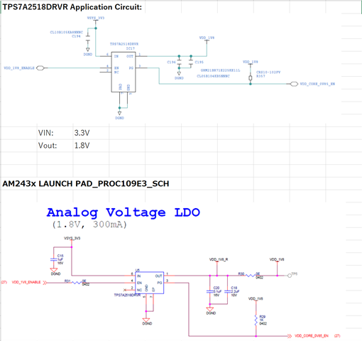
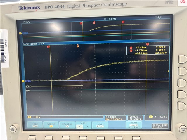
My customer is evaluating the TPS7A2518DRVR for powering the AM2432. Their TPS7A2518 application circuit is based on the AM243x LAUNCH PAD_PROC109E3_SCH. When they measured the TPS7A2518 OUT voltage at startup, it had ~2.5V overshoot at OUT which is higher than the maximum absolute ratings of the AM2432. They also measured the TPS7A2518 OUT voltage at startup on the AM243x LAUNCH PAD, it had the same overshoot.

They tried adding a 12k ohm resistor between OUT and GND in parallel with Cout, but it did not have the effect of reducing overshoot.

TPS7A2518DRVR周辺回路.xlsx

The TPS7A25 seems to have "8.3.7 Active Overshoot Pulldown Circuitry", but it is not effective.

Are there any measures to reduce the OUT overshoot?

Best Regards,

Koshi Ninomiya

  • Hello,

    Thank you for your question.

    Would you be able to measure the output current of the circuit as well and send over an oscilloscope shot of what you are seeing?

    This behavior is completed normal and looks to be happening from inrush current. Vin seems to be drooping from the inrush current, which is normal, and causing the behavior you are seeing on the output. Since the output is only moving about 10mV, this should not be a concern or issue moving forward.

    If you would like to decrease the overshoot on the output, you can add a 10nF Cff cap. 

    If there is excessive capacitance across the FB to GND path, then additional parasitics will be present in that path leading to the destabilization of this loop. If the customer does not already have a Cff capacitor, we recommend adding a 10nF cff capacitor to help restabilize this loop. 

    Hope this helps!

    Best,

    Hannah

  • Hi Hannah-san,

    This parts is the TPS7A2518DRVR, Vout=1.8V fixed version. It does not have a FB pin, so the custoer cannot add a 10nF Cff cap.
    As you can see the measurement results of the customer, Vin, IN voltage of the TPS7A2518DRVR, does not drop as an attached below,

    5554.TPS7A2518DRVR周辺回路.xlsx

    They tried,
     - Added a 12kΩ dummy load between OUT and GND in parallel with Cout.
     - Added a 4.7uF in parallel with a Cin 1uF. Without a 12kΩ resistor between OUT and GND in parallel with Cout.
    However, the TPS7A2518DRVR still has ~2.5V peak overshoot at OUT=1.8V.

    Are there any measures to reduce the OUT overshoot?

    By the way,  does the AM243x LAUNCH PAD ware of this OUT overshoot issue?

    Best Regards,

    Koshi Ninomiya

  • Hi Koshi-san,

    I am sorry for the misunderstanding. 

    Could you please send me a waveform of what you are seeing including Vin, Vout, Ven, and Iout?

    Thanks!

    Hannah

  • Hi Hannah-san,

    I have already attached, but please check below,

    6138.TPS7A2518DRVR周辺回路.xlsx

    Best Regards,

    Koshi Ninomiya

  • Hi Koshi-san,

    Please allow me 2-3 business days to look into this issue for you and get back to you.

    Best,

    Hannah

  • Hi Koshi-san, 

    Has / is the customer willing to add more capacitance to their output? 

    This can help fix output overshoot. 

    Best,

    Hannah

  • Hi Hannah,

    There was no improvemet in Vout Overshoot.
    Please review the attached file below,

    TPS7A2518DRVR_VOUT_Overshoot.xlsx

    Is there a way to improve overshoot?

    Best Regards,

    Koshi Ninomiya

  • Hi Koshi,

    I will look into this first thing tomorrow morning.

    Best,

    Hannah

  • Hi Koshi,

    Did the customer by chance have a scope shot including the load current? The overshoot on the output could be caused from inrush current.

    Best,

    Hannah

  • Hi Hannah-san,

    The customer has asked you to perform actual measurements in the same TPS7A25185 application circuit, and check the output overshoot at startup.

    They really has asked you to check the OUT overshoot at startup.

    Best Regards,

    Koshi Ninomiya

  • Hi Koshi,

    We will get this measurement within 2-3 business days.

    Best,

    Hannah

  • Hello Koshi-san, 

    We have tested this device with the customer's setup and discovered no overshoot. 

    Therefore, we believe this has something to do with the customer's setup.

    Best,

    Hannah

  • Hi Hannah-san,

    Can you please add Vin=3.3V votlage waveform too?

    In case of the customer's setup, measurement waveforms, Vin=3.3V rose up in 1msec, and Vout=1.8V rose up within 100usec.
    However, your Vout measurement waveform, it took 24msec for Vout to rise to 1.8V.

    Best Regards,

    Koshi Ninomiya

  • Hi Koshi-san,

    Please allow us 1-2 business days to take this measurement and get back to you.

    Best,

    Hannah

  • Hi Hannah-san,

    In case of the customer's setup, measurement waveforms, Vin=3.3V rose up in 1msec, and Vout=1.8V rose up within 100usec.
    This Vin=3.3V (= VSYS_3V3) is regulated by the TPS62822 which is the same as the TPS7A2518 application of the AM243x LAUNCH PAD_PROC109E3_SCH.
    Please check an attached file below, and take a close look at the application circuit of the seat "TPS7A2518DRVR Application" and the "Vout_Overshoot".

    4174.TPS7A2518DRVR_VOUT_Overshoot.xlsx

    Please evaluate the same Vin condition.

    Best Regards,

    Koshi Ninomiya

  • Hi Hannah-san,

    How is your evaluation status? We look forward to your evaluation results with the same Vin conditon.

    Best Regards,

    Koshi Ninomiya

  • ,

    Could you please look into this?

    Best,

    Hannah

  • Hello Koshi-san,

    Thank you so much for your patience with this issue. I performed bench testing on our side using the TPS7A2518 fixed 1.8 V device under conditions matching those you described (same input voltage range, typical startup sequence, and similar output capacitance/load). In our measurements, we did not observe an overshoot anywhere near +2.5 V above the intended 1.8 V output rail.

    Below are some points to help reconcile why our measurements show no significant overshoot, while your customer continues to observe it:

    1. Measurement Technique
      • Scope Probe and Ground Lead: If the scope probe has a long ground lead or is creating a ground loop, fast transients at startup can sometimes ring or couple into the measurement, making brief overshoots appear larger than they really are.
      • Bandwidth and Probe Settings: High-bandwidth scope settings can amplify switching noise or ring. Sometimes limiting the scope bandwidth to 20 MHz or using a short “tip-and-barrel” probe adapter (no long ground wire) can significantly reduce apparent overshoot on the waveform.
    2. Board Layout or Additional Parasitics
      • Differences in layout (trace inductances, routing of the input supply, or large ground loops) can cause transient overshoot on the output node. If the customer’s board routing or bypass capacitors are configured differently than TI’s EVM or LaunchPad reference design, it could create conditions for overshoot on startup.
      • Confirm that the output capacitor is placed as close as possible to the LDO’s output and ground pins, and the input capacitor is similarly close to the input and ground pins.
    3. Load Conditions at Startup
      • In our tests, we evaluated both light load (tens of mA) and heavier loads up to the rated current. Under neither condition did we observe an overshoot near 2.5 V.
      • If your customer’s system has external loads or circuits attached to the 1.8 V rail that momentarily source current back into the LDO output (rather than purely sink current), that could push the rail higher momentarily. Checking the system for any back-driving loads would be important.
    4. Potential Workarounds
      • If the customer still sees overshoot after verifying all the above, they might try adding a small RC snubber on the output line (a small resistor, on the order of 1–2 Ω, in series with the output capacitor) to dampen ringing or transient spikes.
      • Ensure they have measured the entire startup sequence (from VIN rising to VOUT stable) with the recommended scope technique, verifying that the overshoot is not simply a measurement artifact.

    If, after reviewing these points, the customer continues to see the large overshoot, please share a detailed scope capture (using short ground leads, including VIN and VOUT on the same plot) so that we can examine the waveform shape in detail. We’d be happy to continue assisting them.

    Hope this helps,

  • Hi Vahnroy-san,

    I have already asked, in case of the customer's setup, measurement waveforms, Vin=3.3V rose up in 1msec, and Vout=1.8V rose up within 100usec.
    This Vin=3.3V (= VSYS_3V3) is regulated by the TPS62822 which is the same as the TPS7A2518 application of the AM243x LAUNCH PAD_PROC109E3_SCH.
    Please check an attached file below, and take a close look at the application circuit of the seat "TPS7A2518DRVR Application" and the "Vout_Overshoot".

    7230.TPS7A2518DRVR_VOUT_Overshoot.xlsx

    Please evaluate the same Vin condition.

    Best Regards,

    Koshi Ninomiya