


Other Parts Discussed in Thread: UC1843
Tool/software:
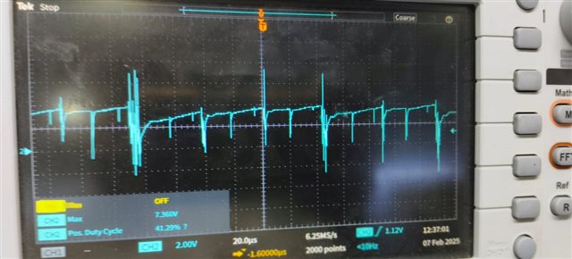
COMPENSATION
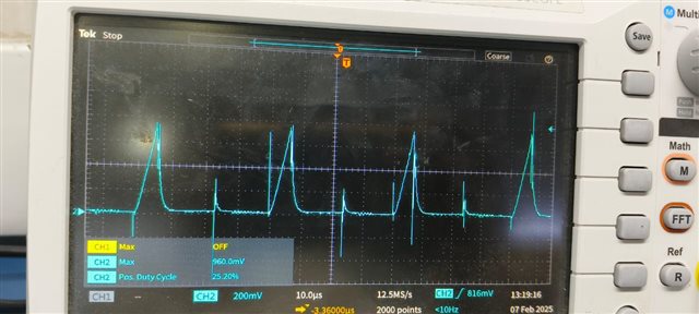
CS PIN
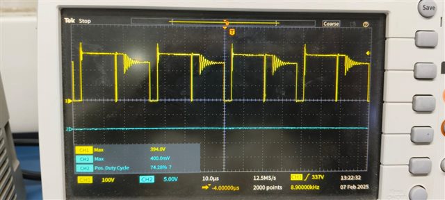
DRAIN TO SOURCE
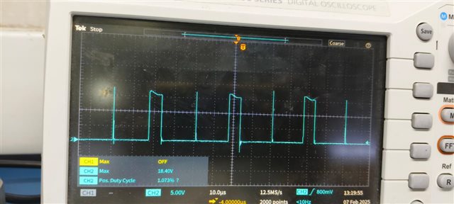
GATE PULSES
Hi I am testing a flyback converter using UC1843.
HERE the specs are Universal input AC-DC.
OUTPUT VOLTAGE IS 15V AND OUTPUT FULL LOAD CURRENT IS 5.5A BUT WORST CASE MAX CURRENT IS 8A.
THE TRANSFORMER RATIO IS 3.5
I AM USING PQ32/20 TRANSFORMER WITH 200uH PRIMARY INDUCTANCE AT 100KHZ SWITCHING FREQUENCY.
I AM USIN THE APPLICATION CIRCUIT AT FIGURE 8.2 OF GIVEN DATASHEET FOR IT.
DATASHEET : UCx84x Current-Mode PWM Controllers datasheet (Rev. H)
NOW I AM FACING AN ISSUE OF NARROW DUTY PULSE AND A 40% DUTY PULSE.
HERE I DONT KNOW WHY ITS LIKE THAT DUE TO SOME REASON I AM OBSERVING THIS OSCILLATION. CAN YOU IDENTI FY THE ISSUE AND HELP ME RESOLVE THIS. I WILL BE SHARING THE WAVEFORMS AND THE VALUES AS PER THE APPLICATION CIRCUIT PROVIDED IN THE DATASHEET.
THA VALUES ARE
CIN = 82uF X 2NOS
RSNUB= 10K, CSNUB IS 10NF, Cvcc IS 100uF ,Rcs is 0.15 ohms Rcsf is 1k Ccsf is 100pf.
transformer Lp = 200uH
NP/NS = NP/NA = 3.5 . Cout is 2200uF/25V
Cvccbp = 1uF Cvref = 0.1uF
Rg is 10 ohms , R bleeder is 10k, Rled is 470 ohms and doesnt have any zener based regulator it is drived by the same vout.
Rfbu is 12k and the Rfbb is a Potentiometer adjusted accordingly.
Rcompz is 10k Ccompz is 10nf
optocoupler datasheet : tclt1000.pdf it has 100% CTR
Ropto is 20K Rfbg is 5K Ccompp is 10nF Rcompp is 10K
RT IS 18K CT IS 1nF NO SLOPE COMPENSATION BECAUSE EVEN THOUGH THE IC UC1843 IS OF 100 DUTY MKAX. THE REQUIRED MAX DUTY AT LOW INPUT i,e 100VDC IS 31% DUTY . SO NOT IMPLEMENTED. CSS IS 2.2uF AND Rss is 10k.
and till 3A its working fine but as soon as i apply 3.7 a load or beyond its oscillating. and i observe the audible noise as i increase the load.
i will share the corresponding comp Cs and Vds and GATE WAVEFORMS IN THE ATTACHMENTS.
AND THE VCC IS STABLE NO ISSUES IN IT .
