This thread has been locked.

If you have a related question, please click the "Ask a related question" button in the top right corner. The newly created question will be automatically linked to this question.

TPS546D24A: transient test

Part Number: TPS546D24A

Tool/software:

Hi team,

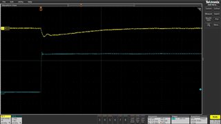
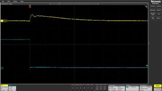
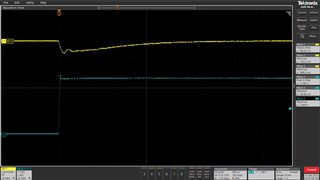
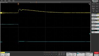
Would you have TPS546D24A EVM on hand can support us test below transient condition?

Vin=12V; Vo=0.8V; Io=0.5A~36A,51.2ns=>>slew rate=700A/us

Thanks!

  • Hi Jeff,

    I have the TPS546D24A 2-Phase EVM, but 700A/us is too fast. The best we could achieve is approximately 100A/us. Please let me know if this works for you.

    Thank you,
    Tomoya

  • Hi Tomoya,

    100A/us is fine. Would you please help us for the Vin=12V; Vo=0.8V; Io=0.5A~36A(51.2ns for 36A) =>>slew rate=100A/us transient test?

    And another question, if we want to evaluate that the DC-DC transient drop does not exceed a certain amount (e.g., 50/100mV),

    is there a way to calculate what the load step rate should be below? Or we need via simulation to check?

    Thanks!

    Jeff

  • Hi Jeff, 

    Please find below the transient test result.

    For the given application setting, the highest achievable slew rate was ~36A/us. Channel 2 (in BLUE) represents the output current, where 1V corresponds to 10A. 

    To estimate this, we offer multiple resources. You can use our simulation models in SIMPLIS or PSPICE:

    https://www.ti.com/product/TPS546D24A#design-tools-simulation

    Alternatively, you may use our Excel calculator, which provides undershoot and overshoot estimations: https://www.ti.com/tool/download/SLURB01

    Thank you,

    Tomoya

  • Hi Tomoya,

    Sorry, Would you please help us shows the CH1 /CH2 peak-to-peak, Maximum and minimum? thanks!

  • Hi Jeff,

    Here is a retake of the waveform, now showing the peak-to-peak, minimum, and maximum values.

    Thank you,
    Tomoya

  • Hi Tomoya,

    thanks for your support!

  • Hi Tomoya,

    I would like to know is TPS546D24A possible to support 700A/uS transient respones?

    Or we just can via simulation to know? thanks!

    Jeff

  • Hi Jeff,

    From the converter's perspective, any rise time that is faster than the PWM clock period is effectively irrelevant. At that point, the behavior is determined solely by the output capacitor and layout parasitic. Therefore, you won't notice a significant difference between testing at 700A/µs (50 ns rise time) and 36A/µs (1 µs rise time) since the PWM clock period is greater. If you would like to verify this, you'll need to perform a simulation. We provide SIMPLIS or PSPICE models:

    https://www.ti.com/product/TPS546D24A#design-tools-simulation

    Thank you,
    Tomoya

  • Hi Tomoya,

    Got it, thanks!

  • Hi Tomoya,

    1. Additionally, could you recommend the values of inductance and capacitance for a 700A/µs case?

    2. Continuing from the above, is there a specific type of capacitor that is required? Tantalum capacitor, electrolytic capacitor, or is MLCC sufficient? The reason for this question is that ESR might affect transient response capability.

      Thanks!
  • Hi Tomoya,

    3. If the input voltage is changed from 12V to 5V or 3.3V, with Vo=0.75V, will changing the input voltage improve the transient response capability?

    According to the buck converter output voltage formula Vo=Vin*D: a. Vin=12V, Vo=0.75V, Duty=0.0625 b. Vin=3.3V, Vo=0.75V, Duty=0.22727

    Theoretically, a lower input voltage results in a greater duty cycle, which means the ON-time of the switch is longer. When there is a sudden large load change, a greater duty cycle would allow more energy to be supplied, potentially improving transient response. Is this understanding correct?

    Thanks!

  • Hi Jeff,

    Tomoya will respond to this in a few days.

    Thanks,

    Calan

  • Hi Jeff,

    Additionally, could you recommend the values of inductance and capacitance for a 700A/µs case?

    I recommend using our Excel design tool, which I will attach below. In this tool, you can enter the load step and the undershoot and overshoot voltage specifications. It will provide you with the recommended output inductance and capacitance, as well as the loop compensation needed for the transient performance you want. It will also estimate the undershoot and overshoot based on your inputs.

    6567.TPS546x24A_ExcelCalculator_SchematicLayoutChecklist_bodeplot_V2p1.xlsx

    Continuing from the above, is there a specific type of capacitor that is required? Tantalum capacitor, electrolytic capacitor, or is MLCC sufficient? The reason for this question is that ESR might affect transient response capability.

    The design tool will show you the required output capacitance. We usually use a mix of ceramic and bulk capacitors to achieve low output impedance across different frequencies. Ceramic capacitors handle high-frequency ripple well because they have low ESR, while bulk capacitors offer larger capacitance to manage significant changes in load current. You can find details about the components we used in our EVM user’s guide.

    https://www.ti.com/lit/ug/sluuc47a/sluuc47a.pdf

    3. If the input voltage is changed from 12V to 5V or 3.3V, with Vo=0.75V, will changing the input voltage improve the transient response capability?

    According to the buck converter output voltage formula Vo=Vin*D: a. Vin=12V, Vo=0.75V, Duty=0.0625 b. Vin=3.3V, Vo=0.75V, Duty=0.22727

    Theoretically, a lower input voltage results in a greater duty cycle, which means the ON-time of the switch is longer. When there is a sudden large load change, a greater duty cycle would allow more energy to be supplied, potentially improving transient response. Is this understanding correct?

    The energy levels will be higher with a higher input voltage (Vin) because this causes more inductor ripple, which may help reduce undershoot a bit. The datasheet has an equation for estimating overshoot and undershoot in the applications section.

    Thank you,
    Tomoya