This thread has been locked.

If you have a related question, please click the "Ask a related question" button in the top right corner. The newly created question will be automatically linked to this question.

BQ25185: NTC temperature threshold

Part Number: BQ25185
Other Parts Discussed in Thread: BQ25180, BQ25186

Tool/software:

Hi, in my application I have a battery with internal 10k @ 25°C NTC resistor connected to a BQ25185. The NTC has the same temperature profile as the 103AT-2 suggested here: https://e2e.ti.com/support/power-management-group/power-management/f/power-management-forum/1308117/bq25185-how-to-select-the-correct-ntc-for-battery-temperature-monitoring

During temperature tests we noticed that the charge is interrupted @ 55°C but the battery can be charged only in the range 5°C - 45°C. The threshold voltage at TS pin when charge is interrupted correspond to the Vhot indicated in the datasheet, so looks like the BQ25185 is ok. 

My question is: what is the temperature range where the BQ25185 allows the battery charging? If I need a different range, how can I adjust the circuit in order to meet my temperature requirements?

Thanks in advance

Alberto

  • Hello Alberto,

    It looks like the issue is that your NTC configuration is causing the charger to detect HOT at 55°C. This can be solved by implementing additional circuitry on the TS/MR pin. The BQ25185 TS function uses an internal current source to bias an external resistor network with the NTC thermistor. The device's HOT and COLD voltage thresholds are designed for a thermistor with β = 3435 and 10k @ 25°C.

    We have an External NTC Monitoring Calculator available on our TI Charger GUI, which can be used to select resistor network values to adjust the HOT and COLD temperatures.

    For the thermistor specifications shown below and a battery temperature range of 5°C to 45°C during charging, use Rs = 100Ω and Rp=352kΩ:

    I recommend checking out this Application Note for more information: Maximizing the Full Potential of NTC Using BQ25180 Linear Charger

    Let me know if you have any questions.

    Best regards,

    Alec

  • Hi Alec, thank you for your response, I will check the AN. My only concern with this solution is that in case of fault of Rs or Rp the threshold will change enabling the battery charge outside the correct temperature range.

    Best regards

    Alberto

  • Hello Alberto,

    First, I'd like to clarify that the External NTC Monitoring Calculator was designed for the I2C-controlled devices in the BQ2518x family. This means that adjusting the temperature thresholds in the calculator provides resistor values that do not directly apply to the standalone BQ25185. For the BQ25180/186/188, the temperature thresholds can be adjusted via I2C, which in turn modifies the HOT and COLD voltage thresholds on the TS pin. So, the calculator outputs and resistor values I shared in my previous reply only apply to the BQ25180/186/188.

    Next, it's challenging to select Rs and Rp resistor values that can achieve a 5°C to 45°C battery temperature window when using the 103AT-2 10k NTC. In fact, it would require an NTC with an unrealistically large β to make this work with the BQ25185 TS voltage thresholds. For example, this could work with an NTC thermistor with β=5500 and 10k @ 25°C, as shown by the solid line in the below graph of TS voltage vs. battery temperature:

    The easiest solution would be to use the BQ25186, which has the same package as the BQ25185 and allows configurable TS voltage thresholds via I2C, making it possible to achieve a 5°C to 45°C window with the 103AT-2 10k NTC, Rs=100Ω, and Rp=352kΩ. Please let me know what you think about this option and we can explore it further. In the below graph, notice that the TS voltages at 5°C and 45°C are the configurable COLD and HOT thresholds, respectively:

    Finally, I understand your concern about the battery charging at unsafe temperatures if Rs or Rp somehow happen to fail. The BQ25186 and BQ25185 do not allow charge if they detect that the TS pin is open. Additionally, these devices each have an active voltage clamp that will prevent the voltage on the TS/MR pin from rising above the VTS_CLAMP threshold. If you could provide additional context for your concern, such as a resistor not being populated or something, that will help me better address it.

    Best regards,

    Alec

  • Hello Alec,

    unfortunately changing the temperature thresholds using I2C is not possible, the charger needs to work standalone. I think that I will look for other chargers that meet my requirements. Anyway thank you so much for your support!

    Best regards,

    Alberto

  • Hello Alberto,

    Thanks for the update. I understand your need for a standalone charger. If you revisit this or need help finding an alternative, feel free to reach out - I'd be happy to help!

    Best regards,

    Alec

  • Hi Alec,

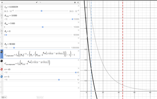
    I have a similar situation to Alberto's, where the battery has a limit of 45°C for charging. By the way, I found it interesting to use the tool to generate graphs of TS voltage vs. battery temperature. I tried to replicate the formula, but the result is different, as below:


    Could you share the link to your graph or point out the error?

    What does the value 273.15 correspond to in the formula?


    Best regards,

    Marcos

  • Hello Marcos,

    Thanks for reaching out. Try copy and pasting this for CCompensated:

    C_{compensated}=I_{TS}\left(\left(R_{P}\right)^{-1}+\left(R_{S}+\left(R_{NTC}\cdot e^{B_{eta}\left(\frac{1}{x+273.15}-\frac{1}{25+273.15}\right)}\right)\right)^{-1}\right)^{-1}

    The 273.15 converts Celsius to Kelvin to keep consistent units in the equation. Let me know if you have any other questions.

    Best regards,

    Alec

  • It worked! Thank you!

  • Hello Marcos,

    No problem—I'm glad it worked! Feel free to reach out if you have any other questions.

    Best regards,

    Alec