This thread has been locked.

If you have a related question, please click the "Ask a related question" button in the top right corner. The newly created question will be automatically linked to this question.

TPSF12C1: Noise reduction effect is not seen

Part Number: TPSF12C1

Tool/software:

Hi support team all.

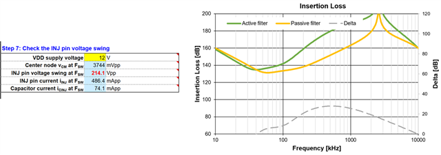
We received a report from a customer that they used a design tool to create a design, but saw little effect in reducing noise.
I have attached the Excel tool.
Could you please give us some advice on what adjustments we should make going forward?

Best regards,

Higa

TPSF12Cx-Q1_quickstart_calculator_A9_PFC4kW.xlsm

  • Hi Higa-san,

    The apps eng responsible for this product is OOO. He will respond when he is back.

    Ben

  • Hi Ben-san

    When do you think AE will be able to respond?

    Best regards,

    Higa

  • Hi Higa,

    I have added Abhijeet who may be able to chime in on this thread. The main AE will be back on the 24th of Feb.

    Ben

  • Hi Higa san

    Thanks for attaching the quick start calculator! Looking at it I can see that AEF INJ pin is saturating for given set of system parameters (Sept 7 of quick start calculator). Can you share customer AEF schematic and how it is connected to their EMI filter. Also we need customers to input CM choke impedance vs frequency data in QuickStart in order to accurately model and calculate AEF components. Can you check if customer has followed this step

    When AEF saturates then there will be no active EMI filtering. Customer can probe the INJ pin of the device to check if AEF INJ pin is saturating or not.

    If they find AEF INJ pin is saturating then they can try out following debug steps

    1. Please check with the customer if they can increase regulator side Y capacitors (from 2.2nF to 6.8nF or so)

    2. Can you check how much is the Y capacitor limitation they have for their system. Is it possible to increase CINJ from 4.7nF to 10nF or higher?

    3. They can increase the values of Cd1 and Cd3 (22nF or higher) and adjust the damping response to bring AEF device out of saturation

    4. Increase VDD voltage to 16V 

    Thanks & Regards

    Abhijeet

  • Hi Abhijeet-san

    Thank you for your reply.

    I will confirm your inquiry with my customer.

    I would like to confirm some things so that I can understand your question correctly.

      You said : Looking at it I can see that AEF INJ pin is saturating for given set of system parameters (Sept 7 of quick start calculator).

                          Question1 :  Is the part you are referring to correct in the following part of the quick start calculator?


          You said :  Also we need customers to input CM choke impedance vs frequency data in QuickStart in order to accurately model and calculate AEF components. Can you check if customer has followed this step?

                          Question2 : Does this mean that I need to manually enter all the values ​​in the "CM choke" tab of the Quick Start Calculator?

       You said : Customer can probe the INJ pin of the device to check if AEF INJ pin is saturating or not.

                          Question3 : How do I check the INJ pin? Should I check the voltage? How do I know if it is saturated?

    I will share their circuit diagram.

    Best regards,

    Higa

  • Hi Abhijeet-san

    Could you please check it?

    Best regards,

    Higa

  • Hello Higa san

    Please find response to your questions

    1. Yes step 7 in customer quick start calculator shows that INJ pin swing is 214Vpp while device VDD is 12V only. So we should keep INJ pin swing within VDD range of the device (as per DS spec) which usually comes to about 9Vpp or so.

    2. Customer can measure this data using impedance meter or choke manufacturer should be able to provide this data in required format. You can copy paste this data in tab 2 of quick start calculator


    3. You should probe at INJ pin of the device. When AEF is not saturated you should see sine wave like signature on INJ pin. When AEF is saturated you can see that peaks are clipping as INJ pin hits VDD rail (it looks more like a trapezoidal waveform when zoomed in)

    Hope this helps

    Thanks & Regards

    Abhijeet

  • Hi Abhijeet-san

    Thank you for your advise.

    I understood well.

    I will  let me confirm to my customer.

    By the way, I got customer's schematics and board layout information.

    Could you check it?

    Furthermore, as this information cannot be made public, I would like to send it to you via private message, so could you please let me know your email address?

    Best regards,

    Higa