Part Number: LM5146DESIGN-CALC
Other Parts Discussed in Thread: LM5146, LM5146-Q1
Tool/software:
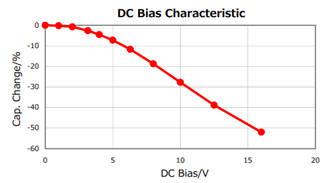
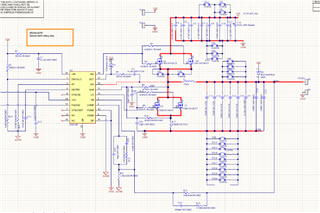
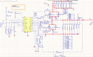
For an input voltage of 28V to 60V, the output specs required are 12V, 8A output.
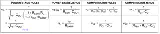
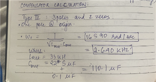
I calculated the compensation network based on the inductor (whose calculation was done based on buck converter inductor calculation) and output capacitance (kept same as that given in the datasheet) mentioned in the schematic below. The type three compensator given in LM5146 used pole placement method for controller calculation. I took L value as 33uH and output capacitance as 110.1uF.
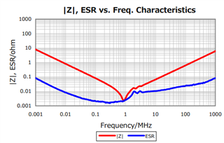
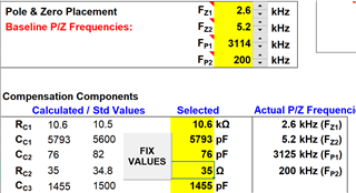
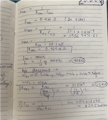
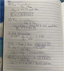
In the datasheet they mentioned poles and zeros placement assumptions, I took those assumptions and calculated compensator network values. Could someone verify the same? I took Cout same as what was given in EVM of LM5146 Q1 for keeping the Resr of output capacitance same so that ωesr doesn't change, which in-turn makes sure ωp2 remains same. Can someone verify the compensator network calculations?
For ILIM calculation I kept both options of Rds(on) sensing and shunt resistor sensing, but in the board, I have populated the shunt resistor sensing option (R16, R17, C20) and (DNP: C3 and R6)
The output voltage however, is coming out to be 3.6V instead of 12V. Could someone let me know what changes can be made to the compensator network and if the power section calculations are correct. The switching frequency of the converter is 400KHz.

 For better clarity.