This thread has been locked.

If you have a related question, please click the "Ask a related question" button in the top right corner. The newly created question will be automatically linked to this question.

UCC5870-Q1: nFLT2 going low when SPI communication is done

Part Number: UCC5870-Q1

Tool/software:

Hi, I'm using this code in CCS with F280025c to write UVLO1 level in config1 register. But thd moment i am running the code, nFLT2 goes low. what i feel is somehow adressing is wrong but i am unable to figure where.

I am first setting the register by WR_RA command given in datasheet table 7-3 then changing lower bits WRL. Please help

This is my code: 

//UCC5870-Q1 Configuration using TI F280025C
#include "F28002x_Device.h" // Include F280025C header file
#include "driverlib.h" // Include TI driver library
#include "device.h" // Include device-specific definitions

// Define SPI settings
#define SPI_BAUD_RATE 1000000 // 1 MHz
#define SPI_CLK_POLARITY 0 // Clock polarity
#define SPI_CLK_PHASE 1 // Clock phase

// Define GPIO pins for SPI on LaunchPad
#define SPI_CS_PIN 10 // Chip select (use GPIO10)
#define SPI_MISO_PIN GPIO_17_SPIA_SOMI // SDO (use GPIO17)
#define SPI_MOSI_PIN GPIO_16_SPIA_SIMO // SDI (use GPIO16)
#define SPI_CLK_PIN GPIO_9_SPIA_CLK
// Define CHIP Address
#define CHIP_ADDR 0x0 // Default chip address


volatile uint8_t faultDetected = 0;
// Function prototypes
void setupSPI(void);
void writeUCC5870(uint16_t regAddr, uint16_t data);
uint16_t readUCC5870(uint16_t regAddr);
void configureUCC5870(void);
void checkFaultStatus(void);


void enterConfiguration2(void);
void exitConfiguration2(void);


void main(void) {
// Initialize device
Device_init();
Device_initGPIO();

// Setup SPI
setupSPI();

// Configure UCC5870
configureUCC5870();

while(1) {
// Main loop
}
}

void setupSPI(void) {
// Configure GPIO pins for SPI on LaunchPad
GPIO_setPinConfig(SPI_MOSI_PIN); // Configure MOSI
GPIO_setPinConfig(SPI_MISO_PIN); // Configure MISO
GPIO_setPinConfig(SPI_CLK_PIN); // Configure CLK
GPIO_setPinConfig(GPIO_10_GPIO10);
GPIO_setDirectionMode(SPI_CS_PIN, GPIO_DIR_MODE_OUT); // Set CS as output

// Configure SPI
SPI_setConfig(SPIA_BASE, DEVICE_LSPCLK_FREQ, SPI_PROT_POL0PHA1, SPI_MODE_MASTER, SPI_BAUD_RATE, 16);
SPI_enableModule(SPIA_BASE);
SPI_setEmulationMode(SPIA_BASE, SPI_EMULATION_FREE_RUN);
}

void writeUCC5870(uint16_t regAddr, uint16_t data)
{
GPIO_writePin(SPI_CS_PIN, 0); // Pull CS low
// Step 1: Set Register Address using WR_RA (0xC)
uint16_t command;
command = (CHIP_ADDR << 12) | (0xC << 8) | (regAddr & 0x1F);
SPI_writeDataBlockingNonFIFO(SPIA_BASE, command);
DEVICE_DELAY_US(10);

// Step 2: Write Data using WRL (0xB)
uint16_t txData = ((CHIP_ADDR << 12) | (0xB << 8) | (data & 0xFF));
SPI_writeDataBlockingNonFIFO(SPIA_BASE, txData);

while(SPI_isBusy(SPIA_BASE));
GPIO_writePin(SPI_CS_PIN, 1); // Release CS
}

void configureUCC5870(void) {
// Configure UVLO1 (register address 0x00) with value 0x00
writeUCC5870(0x00, 0x00);
}

This is what i am seeing on oscilloscope (RED- nCS, Blue - CLK, black - SDI)

  • Hi Mohd,

    For clarification, is the nFLT1 pin low after the device is powered up or is it low after a SPI command?

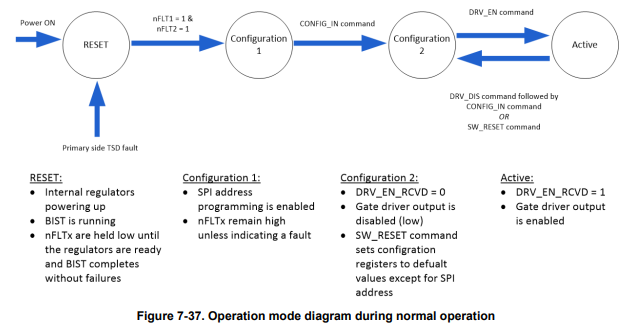
    Your code does not look like it is following the flow diagram to put UCC5870 into the proper operation mode to configure the device. It looks like you are trying to write to CFG1 (0x00) to configure the UVLO1 without entering the Configuration 2 mode.

  • in order to write first we have to go to config 2 and then use wr_RA command then use WRH or WRL depending on which bit we need to program right?
    and for reading we have to use RD_DATA command with register name right?
    but its not giving me data on the sdo line after i am done writing in the register. although now no FLT pin is triggered, so i am hoping writing is happening. Can you check, this is the updated code:


    //UCC5870-Q1 Configuration using TI F280025C
    #include "F28002x_Device.h" // Include F280025C header file
    #include "driverlib.h" // Include TI driver library
    #include "device.h" // Include device-specific definitions

    // Define SPI settings
    #define SPI_BAUD_RATE 1000000 // 1 MHz
    #define SPI_CLK_POLARITY 0 // Clock polarity
    #define SPI_CLK_PHASE 1 // Clock phase

    // Define GPIO pins for SPI on LaunchPad
    #define SPI_CS_PIN 10 // Chip select (use GPIO10)
    #define SPI_MISO_PIN GPIO_17_SPIA_SOMI // SDO (use GPIO17)
    #define SPI_MOSI_PIN GPIO_16_SPIA_SIMO // SDI (use GPIO16)
    #define SPI_CLK_PIN GPIO_9_SPIA_CLK
    // Define CHIP Address
    #define CHIP_ADDR 0x0 // Default chip address

    volatile uint8_t faultDetected = 0;
    // Function prototypes
    void setupSPI(void);
    void sendWR_RA(uint16_t regAddr);
    void writeUCC5870(uint16_t data);
    void configureCOMMANDUCC5870(void);
    void enterConfiguration2(void);
    void exitConfiguration2(void);
    void enterConfigMode();
    uint16_t readUCC5870(uint16_t regAddr);
    volatile uint16_t regVal = 0; // Make it global


    void main(void) {
    // Initialize device
    Device_init();
    Device_initGPIO();

    // Setup SPI
    setupSPI();

    GPIO_writePin(SPI_CS_PIN, 0);
    DEVICE_DELAY_US(20);

    // Configure UCC5870
    enterConfigMode(); // The CONFIG_IN command (see Table 7-3) sent to transition to the Configuration 2 state required for programming device configurations via MCU [1111 0010 0010 0010]
    DEVICE_DELAY_US(10);

    // enterConfiguration2();
    // exitConfiguration2();
    configureCOMMANDUCC5870();

    DEVICE_DELAY_US(40);
    GPIO_writePin(SPI_CS_PIN, 1);

    DEVICE_DELAY_US(20);
    GPIO_writePin(SPI_CS_PIN, 0);
    writeUCC5870(0x20);
    DEVICE_DELAY_US(20);
    GPIO_writePin(SPI_CS_PIN, 1);


    while(1)
    {
    // Main loop
    }
    }

    void setupSPI(void) {
    // Configure GPIO pins for SPI on LaunchPad
    GPIO_setPinConfig(SPI_MOSI_PIN); // Configure MOSI
    GPIO_setPinConfig(SPI_MISO_PIN); // Configure MISO
    GPIO_setPinConfig(SPI_CLK_PIN); // Configure CLK
    GPIO_setPinConfig(SPI_CS_PIN);
    GPIO_setDirectionMode(SPI_CS_PIN, GPIO_DIR_MODE_OUT); // Set CS as output

    // Configure SPI
    SPI_setConfig(SPIA_BASE, DEVICE_LSPCLK_FREQ, SPI_PROT_POL0PHA1, SPI_MODE_MASTER, SPI_BAUD_RATE, 16);
    SPI_enableModule(SPIA_BASE);
    SPI_setEmulationMode(SPIA_BASE, SPI_EMULATION_FREE_RUN);
    //
    // GPIO_setPadConfig(SPI_MISO_PIN, GPIO_PIN_TYPE_STD); // Ensure standard input mode
    // GPIO_setQualificationMode(SPI_MISO_PIN, GPIO_QUAL_ASYNC); // Set to asynchronous mode


    }

    void enterConfigMode(void) {
    uint16_t cfgInCommand = 0xF222; // CFG_IN command in 16-bit format 1111 0010 0010 0010

    // GPIO_writePin(SPI_CS_PIN, 0); // Pull CS low
    // DEVICE_DELAY_US(20);
    SPI_writeDataBlockingNonFIFO(SPIA_BASE, cfgInCommand);
    while(SPI_isBusy(SPIA_BASE)); // Wait for transmission to complete
    DEVICE_DELAY_US(20);
    // GPIO_writePin(SPI_CS_PIN, 1); // Pull CS high
    }


    void sendWR_RA(uint16_t regAddr)
    {
    uint16_t command = ((CHIP_ADDR << 12) | (0xC << 8) | (regAddr & 0x1F)); // WR_RA format

    GPIO_writePin(SPI_CS_PIN, 0); // Pull CS low before transaction
    DEVICE_DELAY_US(2); // Small delay for stability

    SPI_writeDataBlockingNonFIFO(SPIA_BASE, command); // Send WR_RA command
    while(SPI_isBusy(SPIA_BASE)); // Wait for SPI transaction to complete

    // GPIO_writePin(SPI_CS_PIN, 1); // Pull CS high after transaction
    }

    void writeUCC5870(uint16_t data)
    {

    while(SPI_isBusy(SPIA_BASE)); // Ensure SPI is idle before starting

    // GPIO_writePin(SPI_CS_PIN, 0); // Pull CS low before writing data
    // DEVICE_DELAY_US(10); // Small delay to stabilize CS line

    // uint16_t txData = ((CHIP_ADDR << 12) | (0xB << 8) | (regAddr << 3) | (data & 0xFF)); // Corrected write command format
    // Define the variable for 00100000

    uint16_t txData = ((CHIP_ADDR << 12) | (0xA << 8) | (data & 0xFF));


    SPI_writeDataBlockingNonFIFO(SPIA_BASE, txData);

    while(SPI_isBusy(SPIA_BASE)); // Wait for SPI transaction to complete

    // DEVICE_DELAY_US(20); // Small delay to ensure complete transmission
    // GPIO_writePin(SPI_CS_PIN, 1); // Release CS only after SPI is done
    }
    //

    uint16_t readUCC5870(uint16_t regAddr)
    {
    uint16_t txData = ((CHIP_ADDR << 12) | (0x1 << 8) | (regAddr << 3)); // Corrected read command format [1111 0001 0000 0000]

    GPIO_writePin(SPI_CS_PIN, 0); // Pull CS low
    DEVICE_DELAY_US(10);
    SPI_writeDataBlockingNonFIFO(SPIA_BASE, txData);
    while(SPI_isBusy(SPIA_BASE));
    SPI_readDataBlockingNonFIFO(SPIA_BASE);
    // DEVICE_DELAY_US(10);
    // GPIO_writePin(SPI_CS_PIN, 1); // Release CS
    // DEVICE_DELAY_US(10); // Small delay

    // SPI_writeDataBlockingNonFIFO(SPIA_BASE, 0xF542); // Send NOP to clock out data
    // while(SPI_isBusy(SPIA_BASE));

    // uint16_t rxData = SPI_readDataBlockingNonFIFO(SPIA_BASE); // Now read the actual register data

    return 0; // Return the valid register data


    }


    //
    //void enterConfiguration2(void)
    //{
    // writeUCC5870(0x1B, 0x0001); // Write to CONTROL1 register to enter Configuration 2
    // DEVICE_DELAY_US(10); // Small delay to allow transition
    //}
    //
    //void exitConfiguration2(void)
    //{
    // writeUCC5870(0x1B, 0x0000); // Exit Configuration 2 if necessary
    //}


    void configureCOMMANDUCC5870(void)
    {
    // Configure UVLO1 (register address 0x00) with value 0x00
    GPIO_writePin(SPI_CS_PIN, 0); // Pull CS low before writing data


    sendWR_RA(0x00); //1111 1100 000[0 0000]
    writeUCC5870(0x20); //1111 1011 0010 0000
    // Read back to verify configuration
    readUCC5870(0x00);

    DEVICE_DELAY_US(20);
    // readUCC5870(0x00);


    }

  • Hi Mohd,

    Could you provide a schematic of your design and the conditions of the supplies? Feel free to send it to me directly, as this is a public forum.

    You should not normally see faults when performing SPI 

  • how do i reply to you privately in this forum?

    Also tell me one thing, if i am using independent slave configuration, what should be put in chip adress for reading and writing data? would 0xF work as it is a  broadcast address? because if i am using 0x0 or 0xF it says in datasheet section 7.5.1.2 as:

    "When an invalid addressed command or 0xF (broadcast address) is received, the SDO returns to high impedance, thereby allowing other devices to take control of the shared MISO (SDO) bus."

  • Hi Mohd,

    I have accepted your friend request, you can now send me your schematic via direct messaging.

    When using independent slave configuration, 0x0 or 0xF can used for all of the devices in the system.

  • Please reply to my private messages!

  • Hi Mohd,

    Apologies for the delay, please check your inbox.

  • Hi Mohd,

    Based off of the waveform, you are likely getting the fault because of a mismatch in your SPI commands. The device will trigger an SPI communication fault is when nCS transitions low and high without receiving a proper amount of SCLK pulses (multiple of 16).

    I am letting a member of the C2000 team know the issue and they will be able to further assist you in correcting your SPI code.

  • This Fault triggering issue was resolved earlier, i already told you. Now the problem is even if the SDI, clock and nCS remains as expected, SDO seems to remain High Z and therefore no reading is possible plus if i dont read and just move forward to enabling the driver by sending , DR_EN its not enabling the driver as the gate voltage remains at -VEE