This thread has been locked.

If you have a related question, please click the "Ask a related question" button in the top right corner. The newly created question will be automatically linked to this question.

TPS54302: Device sink from output?

Part Number: TPS54302

Tool/software:

Greetings,

it seems like I'm experiencing the same problem like described in https://e2e.ti.com/support/power-management-group/power-management/f/power-management-forum/1314203/tps54302-device-sink-from-output .

Unfortunately the answer in that thread was given by private email.

Would you mind shareing the response?

Best regards.

  • Hi Daniel,

    Eric will help on this case. Will give you feedback later. Thanks.

    Aurora

  • Hi Daniel,

    Sorry we can not provide the message that long time ago, but we can analyze your case directly.

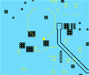
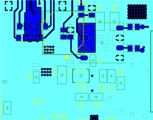
    Could you please share your schematics and layout?

    And what is the working condition for this case, Vin, Vout and Iout?

    What is the RMS current and saturated current of the Inductor on board?

    Thanks.

    Eric

  • Dear Eric,


    thank you for your swift reply.


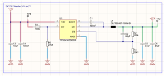
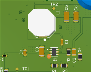
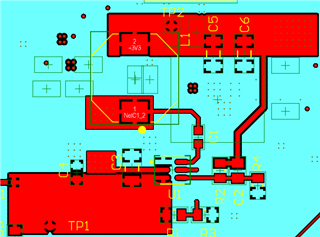
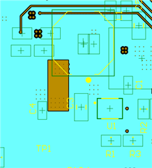
    Attached at the end you will find the schematic and the layout.


    Vin is 24V, Vout is 3.3V, Iout is slightly above 200mA.  

    The saturation current of the coil is 4A, the RMS current is 3.3A.


    It seems like the IC always breaks internally between SW and GND, resulting in a resistive path of ~5Ohms between those two pins. My assumption is that this means that the low-side FET broke, and the 5Ohms might be due to the internal current sense resistor/circuit?

    I had two hypothesizes:

    • ESD issue; however we already broke several ICs, and with ESD I never had an issue in such a continuous/repeatedly way (unless using an ESD gun).
    • In some cases we used a programmer attached to the 3.3V line, which also sourced the voltage, so when we turn off the main power, the device gets reversed sourced (open input and 3.3V external voltage source at the output). However when I use a test setup to intentionally force this condition, the IC is supper resistant, and I’m not able to destroy it using this approach.  


    Any hint is very much appreciated.


    Best regards,

    Daniel


    Layout:

     3D:


    The GND net is highlighted in light blue on every layer.

    Top-Layer:


    Top 1 (Inner layer):


    Bot 1 (Inner layer):


    Bot-Layer:

  • Hi Daniel,

    In some cases we used a programmer attached to the 3.3V line, which also sourced the voltage, so when we turn off the main power, the device gets reversed sourced (open input and 3.3V external voltage source at the output). However when I use a test setup to intentionally force this condition, the IC is supper resistant, and I’m not able to destroy it using this approach.  

    I think this may be the root cause of the broken issue. The schematic and layout seems OK.

    Please make sure the external power supply tied to 3.3V output is always turned off and see if this broken issue happens again.

    Best Regards,

    Eric

  • Dear Eric,

    since I wanted to be sure that the external supply via the programmer caused the issue, I did some testing. I used a second laboratory supply with 3.3V connected directly to the output and "tortured" the DC/DC-converter by switching the input supply on and off plenty of times. But with this setup I was not able to destroy the IC, all of a sudden it behaves tough as hell.

    Of course using the programmer attached to the PC is a different setup (which might introduce additional issues due to unknown grounding schemes), never the less I would feel less worried if I was able to force this failure.

    Anyways, would damaging the device due to a forced outputed voltage by a second source lead to the observed misbehavior? Which always is: a resistive path of ~5Ohms between the SW pin and GND? Does this seem plausible? 

    Best regards,

    Daniel

    P.S.: For the record: the swiftness of your replies and the obvious effort you are putting in, answering the question is very much appreciated.

  • Hi Daniel,

    Thanks for your experiment details. 

    Can you figure out the time when FET is broken? I mean after what action it is broken.

    Then we can go further with that.

    Best Regards.

    Eric 

  • Hi Eric,

    unfortunately I can't tell the time/last action before the device got damaged.

    And right now I can't repeat the unknown damaging procedure.

    Anyways, I guess we came as far as we could regarding this issue. Not connecting an external voltage source is definately going to help the survivability of the device. And not connecting different grounds (laboratory supply, programmer, USB, PC, etc.) might also be a good idea.

    I'll do some more testing, but unless I get new information I guess there is not much we can do right now.

    Best regards,

    Daniel

  • Hi Daniel,

    Anyways, I guess we came as far as we could regarding this issue. Not connecting an external voltage source is definately going to help the survivability of the device. And not connecting different grounds (laboratory supply, programmer, USB, PC, etc.) might also be a good idea.

    Yes, if the issue cannot be repeated, then we can do "What action will not break the FETs".

    If these actions help protect the FET from damaging, those can also be seen as the solutions.

    Best Regards,

    Eric