This thread has been locked.

If you have a related question, please click the "Ask a related question" button in the top right corner. The newly created question will be automatically linked to this question.

UCC14240-Q1: UCC14240-Q1

Part Number: UCC14240-Q1
Other Parts Discussed in Thread: UCC14241-Q1, , UCC21738-Q1

Tool/software:

Hi,

I am trying to use the UCC14240 isolated DC/DC module to drive a pair of UCC5390S.
As far as I understand, it is possible to power the UCC5390S with a dual output voltage generated by the UCC14240.
The UCC14240 should generate the +15V and -5V voltages which power the isolated side of the gate driver.
I am now trying to specify the value of COUT3, but I can't properly interpret the meaning of the parameters listed in the component’s datasheet or how to determine them.

• I(VDD-COM) is the total current from VDD to COM, excluding average gate drive current.

• I(COM-VEE) is the total current from COM to VEE, excluding average gate drive current.

• IQ_DRIVER_VDD-COM is the maximum quiescent current of the gate driver from (VDD – COM), and any current pulled from VDD by external logic must be included.

• IQ_DRIVER_COM-VEE is the maximum quiescent current of the gate driver from (COM – VEE),

• IOther_load_VDD-COM is the maximum current pulled from VDD to COM by external logic.

• IOther_load_COM-VEE is the maximum current pulled from COM to VEE by external logic.

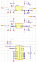
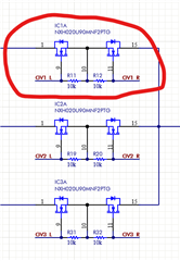
The preliminary schematic is shown below, any suggestions is welcome. 

Best Regards, 
Federico Filosomi 

  • Federico,

    A few recommendations to get you started:

    1. Suggest to use UCC14241-Q1 or UCC15240/1-Q1. All are p-2-p compatible with UCC14240-Q1. Versions that end with "1" are 5kV isolation, versions that end with "0" are 3kV isolation and 15240/1 vs 14241 is 2W vs 1.5W max power capability. The UCC14241-Q1 or UCC15240/1-Q1 have improved noise immunity and longer soft start time to allow more reliable startup compared to UCC14240-Q1. UCC14240-Q1 is the first version TI released and does not have these improvements captured.
    2. It seems you have not used the UCC14241-Q1 Excel Design Tool. The Excel Design Tool will help to answer all the questions you have listed, Download it here and you will see how simple the design setup can be for sizing the capacitors, RLIM, feedback dividers, etc. 
    3. The UCC14240EVM-052 is another good resource to consider and the EVM is already configured for VDD-COM=+15V, VEE-COM=-5V. Even if you do not order the EVM, please download the EVM User Guide here.

    Regards,

    Steve

  • Hi Steve,

    Thank you very much for your tip! It was really helpful, and I have almost completed my work.

    However, I still have a question regarding the usage of Excel, specifically about the split of the IQ_DRIVER current. In the Excel sheet, two parameters are defined:

    • Quiescent current of the gate driver from (VDD – COM): IQ_DRIVER_VDD
    • Quiescent current of the gate driver from (COM – VEE): IQ_DRIVER_VEE

    When reviewing datasheets for several gate drivers, I typically see only one value listed for the quiescent current. For example, in the UCC21738-Q1 datasheet, I only find IVDDQ specified.

    I assume this value corresponds to IQ_DRIVER_VDD (VDD – COM), while IQ_DRIVER_VEE (COM – VEE) should be considered zero.
    Would you mind confirming if my assumption is correct?

    Looking forward to your insights.

    Best regards,
    Federico


  • If only one IQ is provided from the iso gate driver data sheet, then use that value for IQ_DRIVER_VDD and IQ_DRIVER_VEE in the Excel tool. Also recommend to use RLIM configured as RDR as described in the Excel tool. Draw the schematic similar to what is shown in the EVM User Guide (include RDR for RLIM, even though the EVM does not) and when you begin the PCB layout, pay attention to the PCB design guidance in section 12.5 of the UCC14241 data sheet.

    Steve

  • Hi Steve,

    Thanks once again.
    I hope I won't bother you further... :)
    Hopefully, this is the last question:
    May I use the UCC14240 together with the UCC5390S?

    Currently, I’m considering employing the UCC14240 to power two gate drivers:
    UCC21738 and UCC5390S.
    I still have some concerns about whether the UCC14240 can be used to power the second one.

    Regards,

    Federico 


  • Federico,

    There are many examples in three phase inverter for example, where a single UCC14241 is bias all three, low-side iso gate drivers and each of the three high-side iso gate drivers has it's own dedicated bias, only because the high-side discrete are each referenced to a different mid-point for each inverter phase.

    In your case, you can bias both iso gate drivers if:

    1. both gate drivers are driving discretes that are referenced to the same GND
    2. The total power is within the capabilities of the UCC14241. In the Excel tool, enter the total gate charge, Qg, as 2x to account for 2 drivers and this will double the required power from UCC14241.

    Steve

  • Hi Steve, 

    Can I use only one UCC14241 to power both gate drivers of one leg of a Vienna Rectifier?


    Regards, 
    Federico 

  • Same answer as previous. If the UCC14241 can provide the power needed (check result from the Excel spreadsheet) and the gate drivers you are biasing are each referenced to the same GND, then yes.

    Steve