This thread has been locked.

If you have a related question, please click the "Ask a related question" button in the top right corner. The newly created question will be automatically linked to this question.

TPS65987D: USB-C-PD-DUO-EVM The source board does not work after a short circuit on the input power.

Part Number: TPS65987D
Other Parts Discussed in Thread: LM3489

Tool/software:

Hi

The input is 20V. The 3.3V system power is normal.

The output is bypassed by 5V.

The 5V, 9V, 15V, and 20V switches do not work.

The 5V, 9V, 15V, and 20V LEDs do not work.

Therefore, the TPS65987D chip seems to be broken.

Is there a way to know if the chip is broken?

Also, if I replace the chip, will it work regardless of the firmware?

  • Hi Shin Chol Choi,

    When you say a short circuit on the input power, was the 20-V bus shorted?

    The output is bypassed by 5V.

    The 5V, 9V, 15V, and 20V switches do not work.

    The 5V, 9V, 15V, and 20V LEDs do not work.

    Therefore, the TPS65987D chip seems to be broken.

    I've never seen this behavior before, so I can not confirm for sure that it is the TPS65987D chip that is broken.

    Is there a way to know if the chip is broken?

    It's a bit difficult with this EVM but there are some things you can check

    1. Are LDO3V3 and LDO1V8 outputting power?

    2. If you probe the SPI lines (J2) and power the board, do you see SPI traffic that would indicate the PD controller is booting?

    3. If you can connect up to the I2C2 lines (J2), can you try sweeping the I2C addresses on that pin? You should see something ack at 0x20 and 0x21

    Also, if I replace the chip, will it work regardless of the firmware?

    If the TPS65987D chip is the only thing on the EVM that is broken/damaged, replacing the TPS65987DH with another TPS65987DH should work fine. The FW image is stored on the U6 SPI Flash and is loaded when the TPS65987DH boots.

    Thanks and Regards,

    Chris

  • Hi Chistopher

    1. Are LDO3V3 and LDO1V8 outputting power?

    Both 3.3V and 1.8V are correct.

    2. If you probe the SPI lines (J2) and power the board, do you see SPI traffic that would indicate the PD controller is booting?

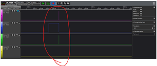
    I checked the SPI signal. It is as shown in the figure below. It seems to be abnormal. Is that correct?

    The red circle is enlarged. There is no change in CSZ signal.

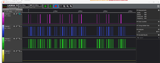
    3. If you can connect up to the I2C2 lines (J2), can you try sweeping the I2C addresses on that pin? You should see something ack at 0x20 and 0x21

    The data is not visible as shown in the picture below.

    Can you please tell me which part you expect to be abnormal?

  • Hi Shin,

    I'll need a couple days to check the SPI lines on an EVM on my side. It does seem unusual the CS does not change level.

    3. If you can connect up to the I2C2 lines (J2), can you try sweeping the I2C addresses on that pin? You should see something ack at 0x20 and 0x21

    The data is not visible as shown in the picture below.

    If the IC is not acking on any I2C addresses while being powered properly, then the IC could be dead. It does look like the I2C lines are toggling so nothing on the lines seem to be forcing it high or low. I'm not too sure what you are showing in the second picture, I'm assuming you are using some I2C host to read from one of the addresses mentioned? Could you zoom in?

    Abnormal would be if the device does not ack at all on any I2C address when powered. I2C2 should always be an I2Ct line.

    Thanks and Regards,

    Chris

  • Hi Chistopher

     I'm assuming you are using some I2C host to read from one of the addresses mentioned? Could you zoom in?

    I enlarged it but there was no change. That's why I didn't attach the enlarged photo.

  • Hi Shin,

    At this point, it may be worth trying to swap the 987 for a new one if you have them on hand. I cannot comment if it is the only thing on the board that may be damaged, but it does seem like the I2C is dead.

    Regarding your concerns about FW, as long as you use the same chip as was on the original DUO-EVM (TPS65987DH) you will be fine. The binary image that configures the part is on the EEPROM, and you can find the pjt file in the 6.1.4 GUI when making a new project.

    Thanks and Regards,

    Chris

  • Hi Chistopher

    I separated the FET (AON7403) from the board.

    I checked the drain and source with a multimeter.

    The FET is shorted in diode mode and shorted in resistor mode.

    Let's try replacing the FET.

  • Hi Shin,

    Is that Q1 on the LM3489? Interesting, may be worth trying.

    Thanks and Regards,

    Chris