This thread has been locked.

If you have a related question, please click the "Ask a related question" button in the top right corner. The newly created question will be automatically linked to this question.

BQ27426: connecting GPOUT to ground to simplify routing

Part Number: BQ27426
Other Parts Discussed in Thread: BQ27427, , BQ27220

We would like to use the BQ27426YZFR battery fuel gauge in our product, but the very small DSBGA package complicates matters: in order to route the VSS pin, we would need to select a more expensive PCB manufacturer capable of achieving smaller trace widths and tighter tollerances, or capable of doing via-in-pad. Our product needs to be very competitive, so we can't afford an increase in PCB cost.

The BQ27427 fuel gauge (with integrated Rsense) would technically solve our issue, since the central VSS pad can be connected to the other VSS pin nearby. This eliminates the issue of routing a small trace between two outer pads. Unfortunately, our product can draw spikes of up to 5A for short periods (at least 500ms), which is above the maximum ratings of the integrated sense resistor.

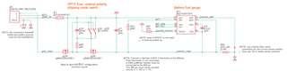
My idea is to use the BQ27426YZFR and route VSS over the GPOUT pin, as shown in this picture:

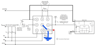
We will not be putting the fuel gauge in SHUTDOWN mode (I don't see a usecase, our product has a power switch), so I don't need GPOUT to exit SHUTDOWN. We also don't need the BAT_LOW signal that GPOUT can provide (as we can just read the state of charge from I²C). Finally, GPOUT is an open-drain output, so there is no risk of short circuit.

The datasheet, however, recommends to add a pull-up resistor if GPOUT is not used:

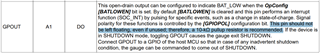
Can I safely get away with connecting GPOUT to VSS and routing over it? I don't want to end up with a malfunctioning fuel gauge that enters a weird state because it senses low on that pin.

Kind regards,

Marco Cipriani

  • Hello Marco,


    To better help you in this case could you attach the images in a different format, we can't view them from our end. 

    Thank you,
    Alan

  • Hello, I fixed the pictures, please let me know for the GPOUT pin, I need this information to continue PCB design

  • Hello Marco,

    This is an acceptable way to route the GPOUT pin.

    Thank you,
    Alan

  • Hello Alan, thank you. In the end, I decided to do low-side current sensing, so I can route VSS over the SRN pin, like so:

    My understanding, from other posts in the forum, is that the fuel gauge is not "characterized" for low-side sensing, so I'm trying to test this circuit using a sample of BQ27426. Do you have any advice or warning for using the fuel gauge in this configuration?

    If this doesn't work, I'll be going back to routing VSS over GPOUT.

    Regards,

    Marco Cipriani

  • Hello Marco,

        Although the system may work route it in the way you have it above, it is heavily not recommend since the chip heavily depends on direct connection to ground. I would follow the image below for schematic phase.

        Also after reviewing the pervious schematic again, it seems that routing VSS over GPOUT should work in the system, but you are running a high risk and lower reward outcome where you could get intermediate wakeup signals to the chip. Most PCB fabs should be able to handle the tolerance needed to run a trace in-between the pins or putting a via under on the pad or next to the pad to get VSS to GND.

  • Hello Alan,

    Where to connect the VSS pin is something I'm a bit concerned about. I did see the "Typical Application" schematic you sent me, but I thought something was off: if VSS is connected to system/load ground, then the gauge is going to see a negative voltage on its SRN pin because the gauge reference is at a higher potential (2A of current through a 10mΩ resistor = 20mV, not much, but also not zero). If the analog circuitry inside the fuel gauge can accurately measure the current even with SRN below zero, then there is no problem. Not every differential amplifier can measure with one or both inputs below ground.

    That's why I chose to connect BQ27426 VSS to battery ground instead of system/load ground, solving the issue of having SRN below zero. What puzzles me the most is that Texas Instruments does exactly like I did in other fuel gauges. For example, here is the reference schematic for the BQ27220 fuel gauge (very similar to the BQ27426, but with CEDV algorithm instead of ImpedanceTrack):

    You can clearly that the ground of the fuel gauge is connected to the negative terminal of the battery (same as in my schematic).

    Now that I thought more about this, I realized the issue with connecting VSS to battery ground: the fuel gauge is going to pull the SDA and SCL lines below ground (again, by 20mV @ 2A). Technically, -20mV is well within the limits of microcontroller GPIOs, so that's ok. If, however, both the microcontroller and the fuel gauge decide to pull SCL or SDA low at the same time, as it could happen during clock stretching, the sense resistor is going to get shorted and 2A is going to flow through the I2C lines, ouch!

    In conclusion, if you can confirm that the fuel gauge will work with SRN below ground, I will modify my schematic like so:

    Regards,

    Marco Cipriani

  • Hello Marco,

    The R sense resistor is used to gauge the flow of current within a system through having a know resistance and being able to determine voltage coming in and out of the resistor. SDA and SCL shouldn't pull below ground since all the ground from the cell and chip are the same it reference that as zero meaning it can't go below the system ground. The way you currently have your schematics setup is correct based on the low side schematic below in page 16. 


    pg 16
    https://www.ti.com/lit/ds/symlink/bq27426.pdf?ts=1740515090222&ref_url=https%253A%252F%252Fwww.ti.com%252Fproduct%252FBQ27426


    Thank you,
    Alan