This thread has been locked.

If you have a related question, please click the "Ask a related question" button in the top right corner. The newly created question will be automatically linked to this question.

TPS7H1111-SEP: Unexplained ouput and input ripples, and large variations at the STAB pin.

Part Number: TPS7H1111-SEP
Other Parts Discussed in Thread: TPS7H4010-SEP, STRIKE

Tool/software:

HI,

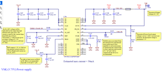
I want to generate a stable power supply of 3.75V using the LDO TPS7H1111MPWPTSEP. For that purpose, I implemented the following circuit. 
The 5V input are coming from a DC/DC the TPS7H4010-SEP whose switching frequeny is set to 350kHz. 

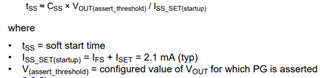
To set the output voltage to the desired level, I connected a Rref=12k to the REF pin and Rset= 37,4k to the SS_REF pin. The Css added in parallel with RSET allows a better stability and a lower output noise and set the soft start time to 7.8ms.

The CLM (current limit mode) is connected to Vin for brick-wall current limit mode.

  Rfbpg_top= 100k and Rfbpg_bot = 10k so that the theoretical threshold output is set to 3.366V.

A capacitor (CCOMP) and resistor (RCOMP) of 4.7 nF and 5 kΩ recommended are placed in series to the STAB pin to compensate the device


When the circuit is power on, here is the scope I obtained for Vout =VSK, the power good signal PG, the Vin= 5V, the SS_REF pin and the STAB pin. 

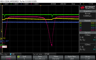
The output ripple at max 30mA load is 169mV and the input ripple 213mV. I also noticed these large falls of the STAB pin signal. The frequency of this phenomenon is 1.2kHz.


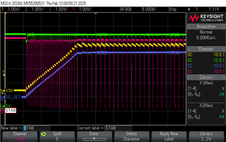
I can not explain what happen, can you help me? 

Do you have an idea of what could cause this? 

Should I do something, modify the configuration to avoid these problems?

Thanks for your help!

  • Hi Elisa,

    At first glance, you schematic values seem reasonable. There are a few things I would like to troubleshoot to narrow down what might be occurring.

    • Do you have any scopes showing the current draw as well as the other waveforms?
    • Does this behavior still occur if the upstream TPS7H4010-SEP is replaced with a bench power supply? 
    • Does this behavior still occur if a larger load is present (perhaps 0.5A)? If the 30mA load is being supplied to downstream circuitry can you also confirm whether the behavior still occurs if that circuitry is disconnected? 
    • Does this behavior still occur if the FB_PG pin is forced high (1V would work)? Startup will be much slower since the 2mA Fast Start current will be disabled.

    As a side note, I calculate your soft start time would be 16ms based on the datasheet equation, not 7.8ms. Your scopes appear to agree. The 7.8ms in the electrical characteristics assumes an FB_PG threshold of ~1.65V, which is different from your configuration. 

    Thanks,

    Sarah

  • Thank you very much for you reply. 
    Indeed, We were not calculating the soft start time correctly. 
    We found the issue, connecting the OUTS pin after the sens resistor was creating this oscillations. 
    We connected the OUTS pin directly at the output of the TPS7H4010-SEP and it solves the issue. 

  • Hi Elisa,

    Thank you for following up with your observations and solution. For my reference, could you share what value the sense resistor was? 

    Also, did you mean the OUTS pin was connected directly to the output of the TPS7H1111? I think it was just a typo, but want to be sure.

    Much appreciated,

    Sarah

  • Hi, 

    Yes it is a 1 Ohm sense resistor. 
    And yes indeed sorry it's a typo. We connected the OUTS pin directly to the output of the TPS7H1111!

    Best regards, 

    Elisa

  • Hi Elisa,

    Thanks for clarifying. A sense resistor that large would definitely impact the dynamics of stability when placed in the path of the control loop. Generally sense resistors are much smaller (mOhms) to lessen power dissipation in higher load applications, so it did not initially strike me as a concern. 

    Your case makes more sense now in light of that detail. Thank you again for following up!

    All the best,

    Sarah