This thread has been locked.

If you have a related question, please click the "Ask a related question" button in the top right corner. The newly created question will be automatically linked to this question.

TIDM-02013: TIDM-02013

Part Number: TIDM-02013
Other Parts Discussed in Thread: PMP22650, C2000WARE, SFRA,

Tool/software:

Hello,

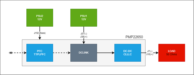
We're evaluating the PMP22650 reference design for a future project.

We've built a board and are testing the application based on the TMS320F28003x microcontroller. The base project we're using is from the tidm_02013 solution available in the C2000Ware DigitalPower SDK (5.04.00.00).

We've started with the CLLLC labs and we manage to complete the first one related to the PWM control of the controller board.

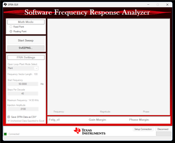
Now we're in Lab 2, where we need to use the SFRA application to characterise the plant and the open-loop parameters of the system.

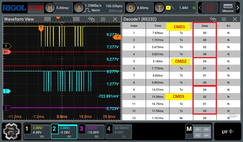
Here we have a problem with the firmware. When we start the SFRA application, the frequency sweep never stops, so we think there must be something wrong with the board application, as we had to make some changes to get it to work.

Code changes introduced to make the example work:

  • obc_7_4kw_user_settings.h:
    • Update the defines to enable SFRA in CLLC.
```
#define OBC_7_4KW_RUN_SFRA_ON_PFC 0
#define OBC_7_4KW_RUN_SFRA_ON_CLLLC 1
```
  • clllc_settings.h: 
    • Update the define CLLLC_SFRA_ALLOWED from the old board define `OBC_6_6KW_RUN_SFRA_ON_CLLLC` to the correct one `OBC_7_4KW_RUN_SFRA_ON_CLLLC`, 
    • Update the lab definition to lab 2.

```

//
// SFRA running on CLLLC
//
#define CLLLC_SFRA_ALLOWED OBC_7_4KW_RUN_SFRA_ON_CLLLC

...

#define CLLLC_LAB 2

```
  • clllc_user_settings.h: 
    • Update the peripheral clock frequency from `50000000' to `30000000', which is required to transmit the SCI data at the correct baud rate.

```

#define CLLLC_SCI_VBUS_CLK 30000000
```
  • ttplpfc_settings.h:
    • This shouldn't make any difference, but we've set the PFC lab to 1 as we're using a DC input on the primary side.

```

#define TTPLPFC_LAB 1
```

Process we followed to run the lab:

  1. Start the debug from ccs.
  2. When the application is stopped in main:
    1. activate the real time mode
    2. start the js script to activate the variables to monitor the clllc lab2
    3. Apply voltage to the primary (10V).
  3. Start the application.
  4. Disable the trim by writing 1 in the 'CLLLC_clearTrip' variable.
  5. At this point we can observe the control PWM switching at the desired frequency (500kHz).
  6. At this point we start the SFRA application and we can connect to the board (connected indicator turns green).
  7. The application starts the sweep and does not change its state (tested for 5 hours).

Is there something we're missing?
We're using the same FW as the laboratory in the documentation?


Thank you for your help.

  • More details on this topic.

    I've captured a command exchange between the SFRA application and the board:

    MCU->GUI

    GUI->MCU

    According to the source code, the command exchange looks like this:

    1. CMD_00: PULSE, Payload 2, LED toggle
    2. CMD_04; GET_VAR, read var group 1, sfra_status. Value 1.
    3. CMD_04; GET_VAR, read var group 2, sfra_frequency_index. Value 0.

    This command sequence is repeated throughout the communication without updating the frequency index.

  • I was able to capture the entire command exchange from the start of the sweep and the moment the application got stuck. These are the commands:

    [0]     { cmd=SFRA_CMD_GET_ARRAY,   size=5,     data=1,     rsp=1112014848  } // get freq start
    [1]     { cmd=SFRA_CMD_GET_ARRAY,   size=6,     data=1,     rsp=1008981770  } // get amplitude
    [2]     { cmd=SFRA_CMD_GET_ARRAY,   size=7,     data=1,     rsp=1065856532  } // get freqStep

    [3]     { cmd=SFRA_CMD_SET_DATA32,  size=0,     data=16968, rsp=1112014848  } // set freqStart
    [4]     { cmd=SFRA_CMD_SET_DATA32,  size=1,     data=15395, rsp=1008981770  }/ / set amplitude

    [5]     { cmd=SFRA_CMD_GET_VAR,     size=0,     data=1,     rsp=100 } // getVar0 vectLen
    [6]     { cmd=SFRA_CMD_GET_VAR,     size=0,     data=1,     rsp=100 }
    [7]     { cmd=SFRA_CMD_GET_VAR,     size=0,     data=1,     rsp=100 }
    [8]     { cmd=SFRA_CMD_GET_VAR,     size=0,     data=1,     rsp=100 }
    [9]     { cmd=SFRA_CMD_GET_VAR,     size=0,     data=1,     rsp=100 }

    [10]    { cmd=SFRA_CMD_GET_VAR,     size=1,     data=1,     rsp=0   } // getVar1 sfra_status

    [11]    { cmd=SFRA_CMD_SET_DATA32,  size=2,     data=16263, rsp=1065850275  } // set freqStep

    [12]    { cmd=SFRA_CMD_GET_VAR,     size=1,     data=1,     rsp=0   } // getVar1 sfra_status
    [13]    { cmd=SFRA_CMD_GET_VAR,     size=1,     data=1,     rsp=0   }
    [14]    { cmd=SFRA_CMD_GET_VAR,     size=1,     data=1,     rsp=0   }
    [15]    { cmd=SFRA_CMD_GET_VAR,     size=1,     data=1,     rsp=0   }
    [16]    { cmd=SFRA_CMD_GET_VAR,     size=1,     data=1,     rsp=0   }
    [17]    { cmd=SFRA_CMD_GET_VAR,     size=1,     data=1,     rsp=0   }
    [18]    { cmd=SFRA_CMD_GET_VAR,     size=1,     data=1,     rsp=0   }
    [19]    { cmd=SFRA_CMD_GET_VAR,     size=1,     data=1,     rsp=0   }
    [20]    { cmd=SFRA_CMD_GET_VAR,     size=1,     data=1,     rsp=0   }

    [21]    { cmd=SFRA_CMD_SET_BUTTON,  size=0,     data=0,     rsp=0   } // Set button: start sweep
    [22]    { cmd=SFRA_CMD_SET_BUTTON,  size=0,     data=1,     rsp=0   }

    [23]    { cmd=SFRA_CMD_GET_VAR,     size=0,     data=1,     rsp=100 } // getVar0 vectLen
    [24]    { cmd=SFRA_CMD_GET_VAR,     size=0,     data=1,     rsp=100 }
    [25]    { cmd=SFRA_CMD_GET_VAR,     size=0,     data=1,     rsp=100 }
    [26]    { cmd=SFRA_CMD_GET_VAR,     size=0,     data=1,     rsp=100 }
    [27]    { cmd=SFRA_CMD_GET_VAR,     size=0,     data=1,     rsp=100 }

    [28]    { cmd=SFRA_CMD_GET_VAR,     size=1,     data=1,     rsp=1   } // getVar1 sfra_status

    [29]    { cmd=SFRA_CMD_GET_VAR,     size=0,     data=1,     rsp=100 } // getVar0 vectLen
    [30]    { cmd=SFRA_CMD_GET_VAR,     size=0,     data=1,     rsp=100 }
    [31]    { cmd=SFRA_CMD_GET_VAR,     size=0,     data=1,     rsp=100 }
    [32]    { cmd=SFRA_CMD_GET_VAR,     size=0,     data=1,     rsp=100 }
    [33]    { cmd=SFRA_CMD_GET_VAR,     size=0,     data=1,     rsp=100 }

    [34]    { cmd=SFRA_CMD_GET_VAR,     size=1,     data=1,     rsp=1   } // getVar1 sfra_status

    [35]    { cmd=SFRA_CMD_GET_VAR,     size=1,     data=1,     rsp=1   } // getVar1 sfra_status
    [36]    { cmd=SFRA_CMD_GET_VAR,     size=2,     data=1,     rsp=0   } // getVar2 freqIndex

    ... in-loop...

    [37]    { cmd=SFRA_CMD_GET_VAR,     size=1,     data=1,     rsp=1   }
    [38]    { cmd=SFRA_CMD_GET_VAR,     size=2,     data=1,     rsp=0   }

    [39]    { cmd=SFRA_CMD_GET_VAR,     size=1,     data=1,     rsp=1   }
    [40]    { cmd=SFRA_CMD_GET_VAR,     size=2,     data=1,     rsp=0   }

    [41]    { cmd=SFRA_CMD_GET_VAR,     size=1,     data=1,     rsp=1   }
    [42]    { cmd=SFRA_CMD_GET_VAR,     size=2,     data=1,     rsp=0   }

    [43]    { cmd=SFRA_CMD_GET_VAR,     size=1,     data=1,     rsp=1   }
    [44]    { cmd=SFRA_CMD_GET_VAR,     size=2,     data=1,     rsp=0   }

    [45]    { cmd=SFRA_CMD_GET_VAR,     size=1,     data=1,     rsp=1   }
    [46]    { cmd=SFRA_CMD_GET_VAR,     size=2,     data=1,     rsp=0   }

    [47]    { cmd=SFRA_CMD_GET_VAR,     size=1,     data=1,     rsp=1   }
    [48]    { cmd=SFRA_CMD_GET_VAR,     size=2,     data=1,     rsp=0   }

    [49]    { cmd=SFRA_CMD_GET_VAR,     size=1,     data=1,     rsp=1   }
    [50]    { cmd=SFRA_CMD_GET_VAR,     size=2,     data=1,     rsp=0   }

  • Hi Sebastian,

    Kindly accept our apologies for the delayed response here.

    Could you share the below details to better understand the root cause.

    1. Power rating of the converter

    2. Input and output voltage ranges and nominal voltage ratings

    3. Share the screen shot of SFRA plot

    Thanks

    Srikanth

  • Hi Srikanth,

    Thanks for your reply.

    To give you some context of the test, this is the test diagram.

    1. We built the same board as the reference design (PMP22650). It should deliver 7.4kW.
    2. At the moment we don't have the disipators mounted on the board, so we're testing with very low values. At the moment we're connecting 12V (limited to 2A) in the DCLink power rail and a load of 50 OHms.
    3. This is the output of the SFRA:

    A few questions on my part:
    - Is it possible to run the SFRA with no load in the system?
    - Is it possible to run the SFRA directly on the controller board without the base with all the power electronics? This would help us to validate that the software controlling the SFRA is working, even if the results are not correct.

    Kind regards,
    Sebastian.
  • One question,

    I read in the forum that the SFRA code can only be executed in the C28 core, but I've noticed that the functions "SFRA_F32_inject" and "SFRA_F32_collect" are executed in the open loop function, which is executed in the CLA core.

    Could this be a problem?

  • Hi Sebastian,

    Yes you can try running it only on controller board without the power converter. Even though it may not give accurate SFRA data, it will make sure the SFRA is working or not.

    Could you also check if you can see any .csv file saved in the  gui folder (C:\ti\c2000\C2000Ware_DigitalPower_SDK_5_02_00_00\libraries\sfra\gui) when you run the SFRA?

    Also, did you try running it at original setting of SCI CLK and Buad rates?

    Thanks

    Srikanth

  • Could you share the snap shot of any lines of code that shows SFRA is running from CLA?

  • Hi Srikanth,

    - I'm using the latest SDK version (5_04), not 5_02.
    - The SFRA does not generate a csv in the same root folder of the gui application.
    - The baud rate of the SCI interface is correct (57600), as you can see in my evidence, communication between MCU and PC is taking place.
    - I'm running the same code as the example in the project
     DigitalPower SDK for reference design TIDM-02013, project <SDK>\solutions\tidm_02013\f28003x. The code executed in the CLA is as follows:

    //
    // Background Task
    //
    __attribute__((interrupt("background")))  void Cla1BackgroundTask ( void )
    {
        #if(CLA_DEBUG == 1)
            __mdebugstop();
        #endif

            CLLLC_HAL_setProfilingGPIO2();


        #if CLLLC_ISR2_RUNNING_ON == CLA_CORE
        #if(CLLLC_LAB == 1 || CLLLC_LAB == 2)
            CLLLC_runOpenLoop();
        #elif(CLLLC_LAB == 3)
            CLLLC_runVoltageLoop();
        #elif(CLLLC_LAB == 4)
        #warning "CLLLC Current Loop has not been validated"
            CLLLC_runCurrentLoop();
        #else
        #warning "undefined CLLLC lab"
        #endif
        #endif


            CLLLC_HAL_resetProfilingGPIO2();

        #if(CLA_DEBUG == 1)
            __mdebugstop();
        #endif
    }

    Inside 'CLLLC_runOpenLoop', toy will finde SFRA code with the following warning (// WARNING: SFRA code only works in C28x CORE!!!):

    #pragma FUNC_ALWAYS_INLINE(CLLLC_runOpenLoop)
    static inline void CLLLC_runOpenLoop(void)
    {
        CLLLC_readSensedSignalsPrimToSecPowerFlow();
        CLLLC_clearPWMTrip();
        CLLLC_modeDetect();
        CLLLC_setCommutatorLC(CLLLC_enableLC);

        //
        // If there is a change in the ref command then set the GPIO
        //
        if(CLLLC_pwmPeriod_pu != CLLLC_pwmPeriodRef_pu ||
           CLLLC_pwmDutyPrim_pu != CLLLC_pwmDutyPrimRef_pu ||
           CLLLC_pwmPhaseShiftPrimSec_ns != CLLLC_pwmPhaseShiftPrimSecRef_ns ||
           CLLLC_pwmPhaseShiftPrimLegs_pu != CLLLC_pwmPhaseShiftPrimLegsRef_pu)
        {
            CLLLC_HAL_setFreqStepChange();
        }

        //
        // Write the Ref values to the active values
        //
    #if(CLLLC_SFRA_TYPE != CLLLC_SFRA_DISABLED)
        // WARNING: SFRA code only works in C28x CORE!!!
        CLLLC_pwmPeriod_pu = CLLLC_SFRA_INJECT(CLLLC_pwmPeriodRef_pu); <------------------ HERE
    #else
        CLLLC_pwmPeriod_pu = CLLLC_pwmPeriodRef_pu;
    #endif

        CLLLC_calculatePWMDutyPeriodPhaseShiftTicks_primToSecPowerFlow();

    #if(CLLLC_SFRA_TYPE == CLLLC_SFRA_VOLTAGE)
        // WARNING: SFRA code only works in C28x CORE!!!
        CLLLC_SFRA_COLLECT(&CLLLC_pwmPeriod_pu, &CLLLC_vSecSensed_pu);<------------------ HERE
    #elif(CLLLC_SFRA_TYPE == CLLLC_SFRA_CURRENT)
        CLLLC_SFRA_COLLECT(&CLLLC_pwmPeriod_pu, &CLLLC_iSecSensed_pu);
    #endif

        CLLLC_HAL_setupISR1Trigger(CLLLC_pwmFrequencyPrev_Hz);
        CLLLC_pwmFrequencyPrev_Hz = CLLLC_pwmFrequency_Hz;

        CLLLC_HAL_resetFreqStepChange();


        CLLLC_HAL_clearISR2PeripheralInterruptFlag();
    }
  • Hi Sebastian,

    Did you try connecting just the MCU board. Make sure you disable the CLLLC protections by setting #define CLLLC_PROTECTION CLLLC_PROTECTION_DISABLED.

    Could you tell us what did you find?

    Thanks

    Srikanth

  • Hi Srikanth,

    I've tested disabling the CLLLC protections in the lab config and it doesn't affect the SFRA behaviour running in CLA. The sweep bar still gets stuck without progressing. I think the definition is related to the trim sources. This feature seems to work fine.

    I've already tested that the SFRA code doesn't work when running in the CLA core, but it does when running in the C28x core.

    My question now is whether this behaviour is correct. If so, I would suggest that this information be included in the design document as there is no mention of it.

  • Hi Sebastian,

    Thanks for checking it. I will check this again and confirm with you soon. In the mean while could share with us how you changed SFRA code from CLA to C28x. Could you share a snapshot with file name.

    Thanks

    Srikanth

  • Thank you Srikanth,

    The SFRA functions are executed in the control loop. In TIDM-02013 you can choose where this code is executed with the definitions in the file "clllc_settings.h".

    Here is an example of how I modify the LAB2 options to run the loop in the C28x instead of the CLA:

    #if CLLLC_LAB == 2
    // #define CLLLC_CONTROL_RUNNING_ON CLA_CORE <--- original line
    #define CLLLC_CONTROL_RUNNING_ON C28x_CORE <--- my change
    #define CLLLC_POWER_FLOW CLLLC_POWER_FLOW_PRIM_SEC
    #define CLLLC_INCR_BUILD CLLLC_OPEN_LOOP_BUILD
    #define CLLLC_TEST_SETUP CLLLC_TEST_SETUP_RES_LOAD
    #define CLLLC_PROTECTION CLLLC_PROTECTION_ENABLED

    #if CLLLC_SFRA_ALLOWED == 1
    #define CLLLC_SFRA_TYPE CLLLC_SFRA_VOLTAGE
    #else
    #define CLLLC_SFRA_TYPE CLLLC_SFRA_DISABLED
    #endif

    #define CLLLC_SFRA_AMPLITUDE (float32_t)CLLLC_SFRA_INJECTION_AMPLITUDE_LEVEL2
    #endif

  • Hi Sebastian,

    Thanks for sharing this. I have confirmed with our SFRA expert. Yes, SFRA can't be run from CLA. Were you able to run SFRA from C28x core. Is it working?

    Thanks

    Srikanth

  • Hi Srikanth,

    After fixing some issues in the serial driver related to the last stage of the process (RETRIVING DATA), I manage to get the bode plot from the tool.

    In case anyone has the same problem, I've modified the "SFRA_GUI_sendData" function to send the data words in the same transmission instead of sending them byte by byte.

    I have all my doubts about the SFRA implementation covered.

    Thanks for the support.

  • Hi Sebastian,

    Just to confirm, did you fix this to run SFRA on CLA?

    Thanks

    Srikanth

  • Hi Srikanth,

    Unfortunately no. This fix was necessary to retrieve the data generated by the SFRA code running on the C28x core.

    Regards.

  • Hi Sebastian,

    Thanks for letting us know. We will take a look at it.

    Thanks

    Srikanth