This thread has been locked.

If you have a related question, please click the "Ask a related question" button in the top right corner. The newly created question will be automatically linked to this question.

BQ40Z60: BQ40Z60 Charge cycle CC, CV and Termination operation

Part Number: BQ40Z60

Tool/software:

Hello,

We have long used a BQ40Z60 in our PCBs for charging a 4S4P battery system.  This question is in reference to the charge cycle from constant current (CC) to constant voltage (CV) transition and eventually the CV to charge termination complete.

We are trying to understand the mode of CV regime shown here.   The datasheet does not explicitly state how the charge current slowly decays (or tapes) until the charge termination is reached.  Is this in a uniform fashion shown in the graph or does the current pulse into the battery while maintaining the charge voltage setting cutoff?

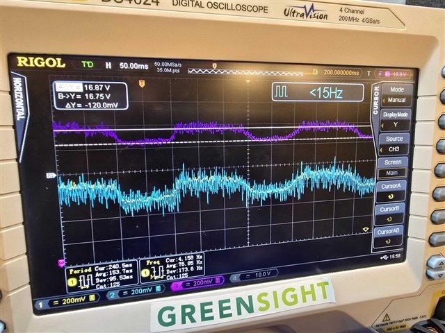
The o-scope capture here shows (difficult with the noise) the voltage at the input to the upper cell of the battery (Charge Termination voltage is set to ~16.75V).

The purple traces it the input to the battery pack, the yellow and light blue are the voltages across the current sense resistor (0.005 ohms) at the output of the buck stage from charger input to the charge / discharge FETs controlled by the BQ40Z60.

This particular observation below occurs as the RSOC is in the upper 90%.

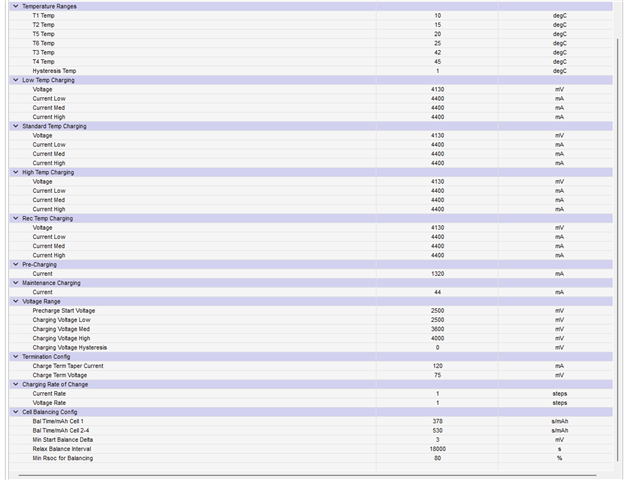
We have other setups that are showing a much larger difference in pulsing (from almost 0 to our Rec Temp Charging Current settings of 4.4A.  These settings are shown here:

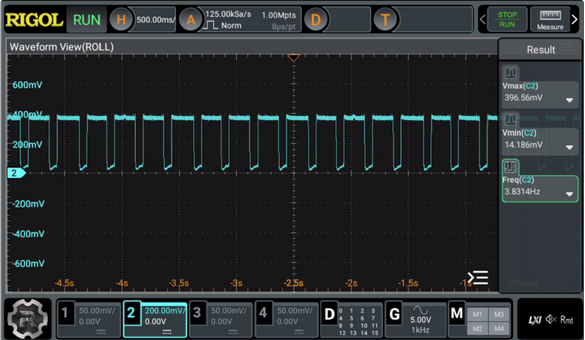
An alternate setup is "chopping" at lower RSOC shown here... jumping to the 4.4A value.

This occurrence below shows an older capture of the transition between CC to CV:

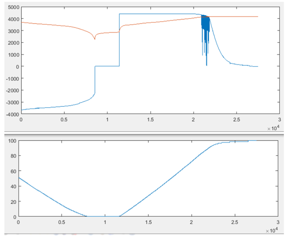
Something to highlight is that our newer versions show the 'chopping' almost all the way to charge termination.

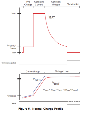
For reference, this what we 'think' the graph should look like.  However, to repeat myself, the CV mode is PWMing at a 3 - 4 Hz time frame all the way to charge termination.

As a note:

The power supplies and / or external charger sources that are plugged in are fully capable of supplying the input power to this circuit as we thought there may have been some external power source dropping out.

We are wondering if TI can shed light on if this is normal or abnormal behavior and if this is an issue for the battery pack itself.

Thank you,

Paul F

  • Hi Paul,

    If possible, please share a .log file of the charge along with the .gg file of the gauge settings so we can look deeper into this.

    Regards,

    Anthony

  • Hi Anthony. Apologies for the delay.   Attached is a short stint of the BQ log file.   I believe we are seeing the issue with the Vacp becoming critically close to the vbat voltages highlighted in the orange rows.  After looking at the ChrgrStat, BattStat and OpStatx columns, it shows charging pausing and then restarting.  During these events, the charging stops, the Vacp relaxes or recovers the input charging voltage (higher than Vbat) and charging resumes.    Our charger is able to provide the current but we are trying to determine if this is noise, an issue with the 10K in series with Vacp and the internal resistance at this input (~40K) or if there is truly IR drop in the system.

    You can see we are charging at 4.4A but th these points, the actual charging current is lower... and most likely noisier with the switching PWM adjusting accordingly. 

    I do have a question about the feedback filtering to the BQ voltage in the schematic. This was copied from the reference design.  Should there not be a filtering capacitor across R26 (lower Resistor of the divider)?  I woudl assume this would help with noise.

      Vbms.log

  • Hi Paul,

    Thank you for sending the log, would it be possible to receive the gauge's current .gg file at this time as well? One thing of note from the image above at this time is that there is a safety alert at this time as well, however it is an OCD alarm and should not interfere with the charging.

    This was copied from the reference design.  Should there not be a filtering capacitor across R26 (lower Resistor of the divider)?  I woudl assume this would help with noise.

    Since this is for a feedback loop, I would not alter what is connected to this loop since the gauge's functionality was most likely tested with these components.

    Regards,

    Anthony

  • Hi Anthony.

    See the GG file attached.

    BQSetting_2-20-25.gg.gg.csv

  • Hi Paul,

    Thank you for sending these files, as you said previously, it does seem like there is something going on with the ACFET with the ACLW and ACFET bits toggling during the periods that it seems like the charge is changing. 

    Can you please go more into depth about what is connected to the adapter at this time.

    Regards,

    Anthony