Tool/software:
Hi,
I am trying to deal with INT_N pin of HD3SS3220RNHR , but no luck. May be you could help me. Here is my case:
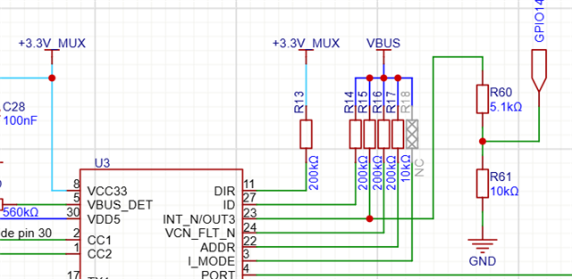
I connect INT_N via pull to 5V and then use divider to get 3v3 and then connect this to a microcontroller (RP2040) GPIO14, please see an image down below. I also have I2C connected to the RP2040 and I can read / write the data without any problem.
My concern is the low state of INT_N pin regardless what I write into a control register:
#define HD3SS3220_ADDR 0x67
#define HD3SS3220_INTERRUPT_PIN 14
...
bool state = gpio_get(HD3SS3220_INTERRUPT_PIN);
while (!state) {
reg_read(i2c_default, HD3SS3220_ADDR, REGISTER_CONNECTION_STATUS, data, 1);
printf("REGISTER_CONNECTION_STATUS: %X\r\n", data[0]);
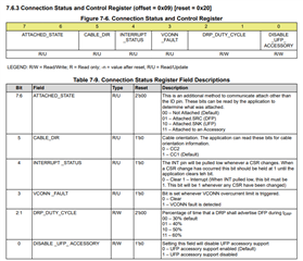
reg_read(i2c_default, HD3SS3220_ADDR, REGISTER_CONNECTION_STATUS_AND_CONTROL, data, 1);
printf("REGISTER_CONNECTION_STATUS_AND_CONTROL: %X\r\n", data[0]);
data[0] = (data[0] & 0xC0) | 0x01;
reg_write(i2c_default, HD3SS3220_ADDR, REGISTER_CONNECTION_STATUS_AND_CONTROL, &data[0], 1);
sleep_ms(10);
state = gpio_get(HD3SS3220_INTERRUPT_PIN);
printf("interrupt pin: %d\r\n", state);
sleep_ms(5000);
}
and the output of the code:
REGISTER_CONNECTION_STATUS: 10
REGISTER_CONNECTION_STATUS_AND_CONTROL: 90
Write operation: 2

interrupt pin: 0
REGISTER_CONNECTION_STATUS: 10
REGISTER_CONNECTION_STATUS_AND_CONTROL: 91
Write operation: 2

interrupt pin: 0
REGISTER_CONNECTION_STATUS: 10
REGISTER_CONNECTION_STATUS_AND_CONTROL: 91
Write operation: 2

interrupt pin: 0
Could you point me what did I do wrong?