A related question is a question created from another question. When the related question is created, it will be automatically linked to the original question.
If you have a related question, please click the "Ask a related question" button in the top right corner. The newly created question will be automatically linked to this question.
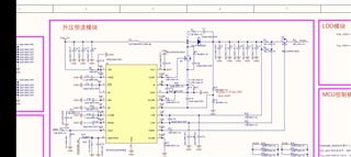
The Voltage RANGE was not shown in the picture and Vout is set to 35V in the picture, not 33V. This is important information for me to evaluate the design. I will get to it ASAP
The vout range is 30-37V, the output current can be divided into two situations: For DRL, the external PWM frequency is 5KHz, the duty cycle is 100%, and the current is 170mA
For position lighting, the external PWM frequency is 5KHz, the duty cycle is 17%, and the current is 29mA
The problem now is that the LED will blink when the duty cycle is in the 30%-70% range, the customer wants to know what could be the cause of the flickering.
I thought this was a preliminary schematic evaluation... I need wave forms when I have to diagnose an issue post-production. However, 5Khz is extremely fast for PWM dimming, we typically recommend under 1KHz to ensure proper resolution and accuracy.
If you would like me to thoroughly diagnose this issue, I will need the following wave forms:
Preliminary design phase:
In the event you are asking me a general question before your customer has begun designing their project,
I need to know the input/ output requirements and switching frequency.
Post design testing phase:
If your customer has an issue with their design and their pcb is already constructed.
I need the following wave forms as well as the input/ output requirements and switching frequency:
Inductor current Switch node voltage fault pin if it is present on the IC Input voltage Output voltage Register settings (if applicable)
any other wave forms that provide me information on the issue that is occurring
I am also more than happy to arrange a meeting with you so we can solve this issue in a timely fashion.
I look forward to assisting you and your customer further.