This thread has been locked.

If you have a related question, please click the "Ask a related question" button in the top right corner. The newly created question will be automatically linked to this question.

UCC28070: PFC Current Transducer Magnetizing Current undrestanding

Part Number: UCC28070

Tool/software:

Hi,
I am designing an Interleaved Continuous Conduction Mode (CCM) PFC Controller using the UCC28070. The PFC will be connected to a universal voltage range of 85–265 VAC. I have selected the boost inductor and output capacitor based on the “UCC28070 300-W Interleaved PFC Pre-Regulator Design” application note, but scaled for a 1000 W output power. The main challenge I am facing now is selecting the appropriate current sense transformer.

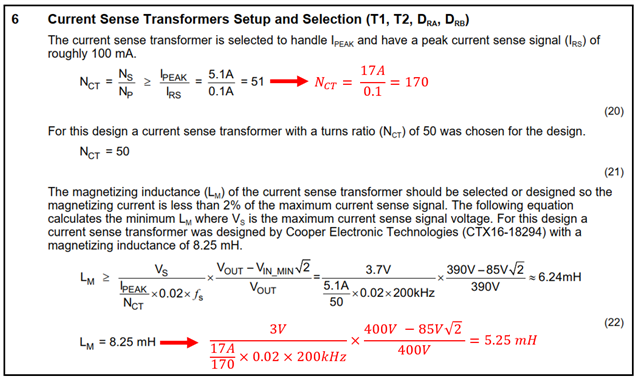
I have calculated the transformer’s turn ratio and magnetizing inductance using the equations below:

Next, I refer to the current sense transformer equivalent circuit shown in the UCC28070 datasheet, which models the transformer’s inductances as the magnetizing inductance (LM) and leakage inductance (LLK).

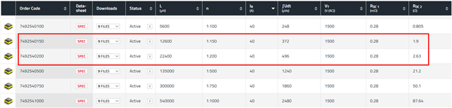
Now see the “749251150” current sense transformer from Wurth Electronics, which has the following parameters:

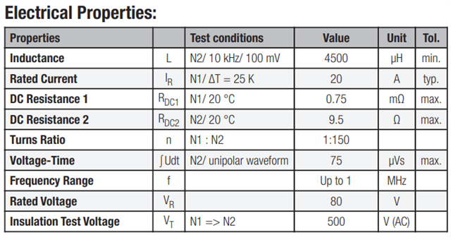
My question is: what is the relationship between the calculated magnetizing inductance (6.295 mH) and the inductance values provided in the datasheet? Is it acceptable to choose a current sense transformer whose inductance matches the calculated magnetizing inductance?

Thanks

MM

  • Hello MM, 

    Yes, the inductance listed in the CT datasheet is the magnetizing inductance of that CT.  

    You should select a CT with inductance equal to or great or than the calculated magnetizing inductance. 
    The main point is to minimize the magnitude of Im (magnetizing current  shown in Figure 25., above) so that the signal obtained at CSx is effectively Rs*Ids/Nct.  

    If Lm is too low, Im "steals" too much current from Ids/Nct and Ids is understated at CSx.  At best this increases THDi, and at worst may allow more peak Ids than expected from the PKLMT setting. 

    Ideally, Lm would be infinite, but that is obviously impracticable so the choice of Lm becomes a feasibility tradeoff between CT size and cost.  

    Regards,
    Ulrich    

  • Hello Ulrich,

    Thank you very much for your timely response, I have one more question:

    I recalculated the parameters for my 1000W PFC controller. The current sense transformer (CT) transfer turn ratio and magnetizing inductance were determined to be 170 and 5.25 mH, respectively, as shown below.

    I am looking to select a CT from Wurth Elektronik, but my options are limited. The available choices are:

    • A CT with a 1:150 turn ratio and 12.6 mH inductance

    • A CT with a 1:200 turn ratio and 22.4 mH inductance

    I prefer the 1:150 CT with 12.6 mH inductance because it offers better current resolution. However, since its inductance (12.6 mH) is significantly higher than the calculated magnetizing inductance (5.25 mH), what potential challenges should I consider?

    MM

  • Hello MM, 

    The 1:150 CT is a fine choice.  
    The turns ratio and inductance does not have to be exact or even very close to what you calculate. 

    The calculations allow you to search the market (or design one) for a suitable item that is reasonably close to your target. 

    The turns-ratio could go either way, here; 150 or 200. 
    The choice of inductance, in my opinion, should always go higher than what you calculate.

    Since both options are higher, secondary considerations would be that 200Turns will have higher series resistance and higher winding capacitance, both parasitics which make reset of the core more challenging.  Here, the 150:1 becomes preferable.  

    Regards,
    Ulrich