This thread has been locked.

If you have a related question, please click the "Ask a related question" button in the top right corner. The newly created question will be automatically linked to this question.

TPS25751: Sink gets periodically hard reset by source

Part Number: TPS25751
Other Parts Discussed in Thread: TPS65982, , TPD6S300, TPD4E05U06, TP600

Tool/software:

Hi,

I'm running into the following issue with the chip. I am using the TPS25751D to sink 5V 3A with the default 15W sink profile from the Application customization tool. My laptop sends hard reset commands when I plug my PCB to it, resulting in the following curve:

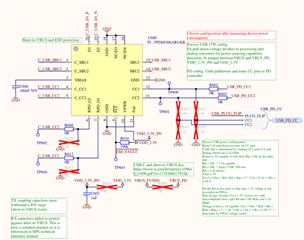
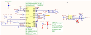
Oddly, this happens on the 15W capable USB-C ports on my laptop but not on the 7.5W capable ones. Here's the schematic around the PD chip:

While investigating, I removed all GPIO mappings. I disconnected loads such that the device drew next to no current. I also changed all config options one by one and only the "PD disable" solved my problem (of course, we would like to keep PD negotiation). I have tried to set the dead battery configuration to AlwaysEnableSink, it did not change the behavior. Finally, I tried to clear the dead battery flag as soon as VDD_1.8V_IO was present (around 0.6 ms after VBUS is available).

This problem does not happen on the same port with another device of ours that uses the TPS65982 with the same 15W profile, drawing 5 to 10W. We have tested other boards and the problem still arises.

I have noticed that applying 3.3V externally to VIN_3V3 before plugging the USB-C cable solved the issue. Our internally generated 3.3V rail is up approximately 4ms after VBUS is applied, and this does not change between the laptop USB ports that work and those that don't.

Do you have any input to help me troubleshoot this issue? I am running out of ideas at this point. Anything will help.

Thanks in advance,

Marc

  • Hi Marc, 

    Can you send the PD log files as well as the JSON configuration for TPS25751? 

    At least based on the screenshot of the PD logs you sent, it doesn't look like the sink TPS25751 system is overdrawing the current limit from the PC (less than USB default current), just to confirm is this connection between the PC to TPS25751 a PD connection (Type-C to Type-C) or is this with a USB-A to USB-C? 

    Thanks and Regards,

    Raymond Lin

  • PD_logs.zip

    Hi Raymond,

    Here are the log files and JSON config. The connection is Type-C to Type-C. It does indeed not look like we are reaching the port's current limit.

    Thanks and regards,

    Marc

  • Hi Marc, 

    Can you send the original TotalPhase PD log file (.tdc) so I can also view the voltage/current waveforms? 

    From the logs you provided, it looks like the source (laptop) is not sending PS_RDY for some reason (not sure if this is due to overcurrent, CC disconnection, some other reason, etc.) but the full PD log file will be able to help us debug further. 

    On your system I see there is an EEPROM on board, however the A0 A1 and A2 pins are all floating. Upon boot-up (either from VBUS in a dead battery state or 3.3V is applied to VIN_3V3), TPS25751 will look for I2C target address 0x50 to load the PD config. I'm not sure how the CAT24C512 would reach if the A0-A2 pins are floating but I would recommend to ground the pins to get the correct I2C target address set for the EEPROM. 

    Thanks and Regards,
    Raymond Lin

  • PD_logs_tdc.zip

    Hi Raymond,

    Thank you for the feedback. Here are the log files in .tdc for successful and unsuccessful connections. They are new captures taken this instant.

    Regarding the EEPROM, the manufacturer's datasheet mentions on-chip pull-downs on the address pins. So normally, leaving them floating should not be an issue. We have successfully flashed different configurations (various sink PDOs, different signals on GPIO...) and have never noticed a failed update. I will look at the I2C bus on bootup, that is a good suggestion.

    We have the TPD6S300 connected to CC pins, it should not cause issues but here's the schematic in case you smell something fishy.

    Is it possible that connecting RPD_G1 and RPD_G2 conflicts with the TPS25751's CC pin handling? I will move the jumpers from R608 to R609 and R612 to R615 while I wait for your reply (EDIT: it did not solve the issue, only blocked PD negotiation).

    Thanks and regards,

    Marc

  • Hi Marc, 

    Quick look at the PD logs, I think we can rule out over-current as the root cause. Both passing and failing logs show roughly around ~500-600mA during the Request->Accept->PS_RDY (in passing log, in fail log no PS_RDY is sent from laptop) unless the laptop has super tight window for how much current can be drawn prior to PS_RDY being sent. 

    On your previous design with TPS65982, did you use any protection device like TPD6S300 or was it a direct connection from USB-C connector to TPS65982? Are you able to try and bypass the TPS6S300 (at least for the CC lines) so that TPS25751 CC lines are connected directly to the USB-C connector? Would lie to see if the protection device is causing any issues there. 

    Thanks and Regards,

    Raymond Lin

  • Hi Raymond,

    On our previous design with TPS65982, CC pins are connected to TPD4E05U06. The negotiation also fails when bypassing the TPD6S300 (connecting TP600 with TP604 and TP601 with TP602). So apparently it doesn't cause the issues.

    I will report any new findings. I am currently testing the rest of the system and with more current draw come more PD issues.

    Thanks and regards,

    Marc

  • I flashed with the low region binary and it worked. Flashed using the full flash binary again and it failed. I'm having trouble setting GPIO configurations, investigating this right now.

    Here is the application customization tool version so we can investigate the issue further

  • Hi Marc, 

    Thanks for the update, I'll check with my team and see if anyone else has encountered anything similar.

    Thanks and Regards,

    Raymond Lin

  • Hi Marc, 

    When you generated the low region binary vs the full flash binary, did you export the binary from the same JSON? Were there any differences in the GUI configuration setting when the binaries were generated? 

    Thanks and Regards,
    Raymond Lin

  • Hi Raymond,

    I have tried to reproduce the issue by generating two binaries from the same JSON. Strangely, the low region binary no longer works in this configuration. I am investigating as of now.

    8080.test.zip

  • test_board2.zip

    I have tried the following files on another board and the full flash binary still has the same problem, but the low region binary works as it did before. I have attached the config file. It looks like we have a hardware issue on the previous board.

  • Hi Marc, 

    Is this issue hardware related? Unless the binaries (low region and full flash) were generated from different JSONs there shouldn't be any difference in behavior. 

    Thanks and Regards,

    Raymond Lin

  • Hi Raymond,

    The low region working and full flash not issues are not hardware related. There is a difference in behavior which I cannot explain, only on some USB-C ports. I took care to generate the binaries from the same configuration and the problem still appears.

    Regards,

    Marc

  • Hi Marc, 

    Apologies for the delayed, looking into the binaries you previous provided (test_board2) to see if there's anything that's differentiating between the two files. 

    For your system, is there any reason why you need both files (full flash and low region)? Are you able to load the PD configuration via I2C from a MCU?

    Thanks and Regards,

    Raymond Lin

  • Hi Raymond,

    Our system has the PD controller set the global power supply enable, so we have no way to load the PD configuration via I2C. We don't need both files, we only need one to work reliably.

    Thanks and regards,

    Marc