Other Parts Discussed in Thread: CSD19538Q3A
Tool/software:
Hello TI Forum Team,
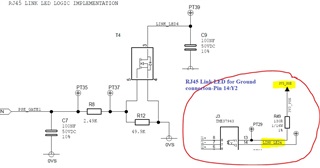
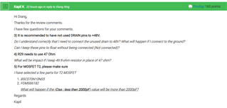
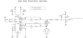
I have created a schematic of PSE controller. It would be highly appreciable if you could review the design. Along with that I have a few queries.
...
Queries:
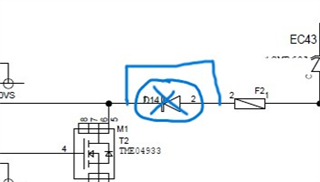
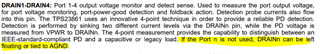
- I have added D14 diode along with F2 fuse for protection. Is it fine? Or No need of this D14 diode?
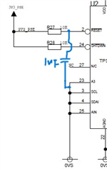
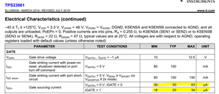
- May I know the Threshold voltage of Gate Pin (1-4)?
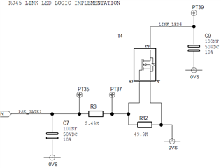
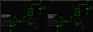
- Can I use this gate pin for LED logic implementation? Making RJ45 Link led terminal to ground.