This thread has been locked.

If you have a related question, please click the "Ask a related question" button in the top right corner. The newly created question will be automatically linked to this question.

BQ25185: Additional Protection Requirements for Intrinsic Safety

Part Number: BQ25185
Other Parts Discussed in Thread: BQ24074

Tool/software:

Hello,

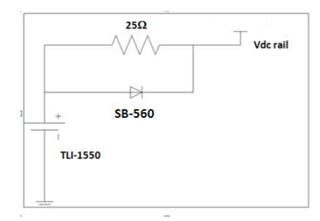
I would like to use the BQ25185 in an intrinsically safe design to be used in hazardous environments. To do so, I am required to add a 25Ω current limiting resistor in parallel with a diode right at the battery prior to connecting to the BQ25185 chip. The current limiting resistor is for limiting charging current and the diode is forward biased in the discharge path. See picture below.

How will these additional components affect the charging ability of the BQ25185 and the ability to discharge from the battery? Is there something I can do to ILIM/VSET and ISET to allow me to use these protection components?

Additionally, I have to protect against multiple faults on the BQ25185 chip, including shorts to all pins. For example, if VIN (5V in my case) was shorted to BAT, would the chip automatically enter fault condition if the battery voltage was 5V? Or do I need to add more protections against this externally from the chip?


Thanks,

Gabe

  • Hello Gabe,

    Before getting into the details, the simplest solution here would be to use a battery protector IC or eFuse if allowed by your application. These devices are designed to handle battery overvoltage, undervoltage, discharge overcurrent, and short circuits more effectively than a resistor. If intrinsic safety allows, this would likely be a more robust approach and avoid some of the trade-offs involved with the 25Ω resistor.

    That said, if you need to pursue the resistor method, there are a few things to consider.

    In battery only mode, the diode will be forward biased and most of the discharge current from the battery will flow through it. But during charging, the diode is reverse biased, meaning all of the charge current current flows through the 25Ω resistor. The IR drop across this resistor will affect the charger's constant voltage (CV) regulation and termination because the charger regulates based on the voltage it sees on the BAT pin. This means that the charger is going to see the battery voltage plus the IR drop.

    One way to compensate for this IR drop is by adjusting the charge regulation voltage (VBATREG). The BQ25185 allows VBATREG to be set to 4.4V, 4.35V, 4.2V, 4.1V, 4.05V, 3.65V, or 3.6V. However, depending on the desired charge current, there is going to be a significant IR drop across the 25Ω resistor, which may make it difficult to choose an optimal VBATREG setting. Additionally, if the 4.35V or 4.4V settings are used, the device will regulate the SYS voltage from the adapter in battery tracking mode, VBAT + 225mV, rather than at 4.5V, as explained in section 8.3.5 of the datasheet. This means that the IR drop of the resistor will likely affect how SYS is regulated in battery tracking mode.

    For short protection, if there's a short to GND or VIN at the BAT pin, the resistor will limit current from the battery for intrinsic safety, as you mentioned. If there's a short to GND on SYS or BAT, the charger's built-in protections will kick in. ISET and ILIM/VSET also monitor for shorts to GND as part of the device's protection features. That said, a VIN-to-battery short is a different scenario. In that case, you'd likely need a battery protector IC to handle overvoltage and prevent external overcurrent. Since the current from the battery wouldn't be going through the internal BATFET nor the 25Ω resistor in that case, the charger's BATOCP wouldn't trigger nor would the battery discharge current be limited. I recommend checking the charger's integrated fault protections (listed on page 1 of the datasheet, more details in section 8.3) and considering additional external protection.

    Let me know if this help or if you'd like to explore other options.

    Best regards,

    Alec

  • Thank you, Alec, for your response. All really good information.

    If we have that 25Ω resistor in series and compensate for that by increasing our charge voltage, will that result in the safety timer going off because the charged battery will not ever reach the charge voltage?

    Gabe

  • Hello Gabe,

    No problem - I'm happy to help.

    If the charge current doesn't reach the termination current before the safety timer expires, the timer will expire. However, I believe the more likely scenario is that the IR drop causes the device to enter CV mode before the actual battery voltage reaches VBATREG.

    For example, let's say the fast charge current is 30mA, creating a 750mV drop across the 25Ω resistor. If VBATREG is set to 4.2V and the actual battery voltage is 3.45V, then the BAT pin would see 4.2V and enter CV mode. As the charger tapers the charge current in CV mode, the IR drop decreases, but charge will still terminate when ICHG = ITERM.

    Since ITERM is 10% of the configured fast charge current, it would be 3mA, resulting in a 75mV IR drop at termination. This means charge would terminate when the actual battery voltage is 4.125V.

    I'd suggest choosing a fast charge current that results in a termination current where the IR drop across the 25Ω allows you to achieve your target battery voltage. Of course, ITERM and the resistor involve accuracy, with ITERM being ±10%.

    Best regards,

    Alec

  • OK, if I understand correctly, in your example, the charger IC would be in CV mode longer than normal use case, since the IR drop is much less due to ITERM. We'd basically be in CV mode from VBAT of 3.45V to 4.125V with a charge current of 3 mA. 

    However, if we are using a 1200 mAh battery, for example, that would mean that we would be in CV mode for roughly 200 hours until our voltage rises to 4.125V (@ 3.45V, battery is at about 50% capacity --> 600 mAh / 3 mA). This is much longer than the safety timer. In this case, something would have to change in the design for this to work. Either the 25Ω would have to be reduced, or the charge current/voltage would have to be adjusted.

    Is this correct?

    Thanks again,

    Gabe

  • Hello Gabe,

    That's right — the charger IC would remain in CV mode much longer than in a typical use case due to the IR drop. And yes, the safety timer would likely expire before charging is completed or terminated in this application.

    Just to clarify one detail: in CV mode, the charge current gradually tapers off from the fast charge current until it reaches ITERM (10% of the fast charge current), at which point charging stops. You're correct that we would be in CV mode from 3.45V to 4.125V, but instead of immediately dropping to 3mA, the charge current will taper down from 30mA.

    If we assume a 1200mAh battery and a constant fast charge current of 30mA, the safety timer would expire (50% capacity at 3.45V –> 600mAh / 30mA = 20 hours). Since a significant portion of charging will occur in CV mode, the timer will almost certainly expire before full charge is reached.

    I agree that this design will need adjustments to work properly. Ideally, reducing the 25Ω would help, but I understand that may not be an option in your application. Let me know what options are available to you, and we can explore them.

    Best regards,

    Alec

  • All makes sense. We will explore our options and see what we can do. Thanks again for your support, much appreciated.

    Gabe

  • Hello Gabe,

    No problem, happy to help. Feel free to reach out if anything else comes up.

    Best regards,

    Alec

  • We actually have documentation available for the BQ24074 to aid functional safety system design. The BQ24074 is essentially the predecessor to the BQ25185, so while this documentation doesn't directly apply to the BQ25185, it may still be a useful reference.

    BQ24074 Pin FMA

    We also have this page, which may be helpful in your system design:

    https://www.ti.com/technologies/functional-safety/products.html#

    Best regards,

    Alec