A related question is a question created from another question. When the related question is created, it will be automatically linked to the original question.
If you have a related question, please click the "Ask a related question" button in the top right corner. The newly created question will be automatically linked to this question.
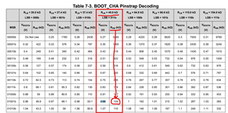
Table 7-3 is broken into columns for each value of RLB. Each column has two sub-columns for VBOOTA and RHB.
To determine the resistor values for a VBOOTA of 0.99V you should find where in the table corresponds to 0.99V then check what RLB column it is in to get the RLB value. The RHB value will be adjacent to the VBOOTA value, in the same RLB column.
By paralleling you are referring to paralleling multiple power stages off one PWM correct? This controller does not have any features for such a setup, so while it could drive multiple power stages from one PWM, the output current used for reporting and fault thresholds would not be correct.
If you need to have more power stages for your application than TPS53676 has PWM channels, you can consider a controller with more PWM channels like TPS536C9T.