This thread has been locked.

If you have a related question, please click the "Ask a related question" button in the top right corner. The newly created question will be automatically linked to this question.

TPS6594-Q1: Details when using the TPS65941515 variant for the DRA821

Part Number: TPS6594-Q1
Other Parts Discussed in Thread: DRA821

Tool/software:

I am using the User’s guide for integrating the TPS65941515-Q1 power management integrated
circuit (PMIC) into a system powering the Automotive JacintoTm 7 DRA821 processor.

I am looking for details on electrical aspects when creating my schematic. For example:

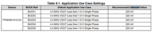
1/ Buck 1&2 outputs are tied together. What value (& current) of inductors do use ?
2/ How do I connect up the feedback pins FB_B1 & FB_B2 ?
3/ Buck 3&4 outputs are tied together. What value (& current) of inductors do use ?
4/ How do I connect up the feedback pins FB_B3 & FB_B4 ?

Thanks,
Steve

  • Hello Steve,

    The User's guide you're referring to is: Single PMIC User's Guide for Jacinto 7 DRA821, PDN-2A

    1)

    2) Please section 11 Layout
    11.1 Layout Guidelines

    from the datasheet for details on how to connect the psuedo differential pairs for BUCKs 1 & 2 along with BUCKs 3 & 4

    3) See the above

    4) See the above

    BR,

    Nicholas McNamara

  • Nicholas,

    Thanks, I note the value for the inductors are 220nH.

    5) But i don't see any CURRENT ratings for the inductors (I intend to use 5V PVIN_B1-5).

    6) In the Layout Guidelines (using the 1515 variant) I cannot see how to connect pin 22 FB_B1, pin 21 FB_B2, pin 49 FB_B3, pin 50 FB_B4.

    Thanks,

    Steve

  • Hello Steve,

    I'll try to find an example of the routing for the combination of BUCK12 & BUCK34.

    In addition I'll let you know the saturation current specifications by end of day tomorrow.

    BR,

    Nicholas McNamara

  • Hello Steve,

    5)Below are screenshots from the datasheet & the User's Guide with the settings for device:

    BUCKs 1, 2, 3, & 4 have the same setting of 5.5A & BUCK5 with 3.5A current forward setting limit.

    With a PVIN of 3V3, being sourced from VCCA, you can calculate the inductors based upon the variance from the above. Since the inductors themselves have variance you may shoot from some percentage above the worst case scenario. Hope this helps.

    6) Below is an example from the processors team EVM with psuedo differential trace to the point of the load (NET on the processor side), NET "VDD_DDR_1V1"

    BR,

    Nicholas McNamara