This thread has been locked.

If you have a related question, please click the "Ask a related question" button in the top right corner. The newly created question will be automatically linked to this question.

UC2526A: Master / Slave Synchronisation for multiple devices

Part Number: UC2526A

Tool/software:

We want to synchronise multiple UC2526A devices but phase shifted relative to each other. We require some guidance on how to achive this.

The approach to synchonise to the same phase that I have observed in the datasheet literature, page 6 of the datasheet to be specific is to have one device as the master, with all CT pins tied to each other between Slave devices as well as the Sync pins tied.

If we want to have each device phase shifted relative to the master do we still tie Slave CT pins to the Master CT pin, but phase shift (delay) the Sync pulse of the Master Sync pulse to be sent to the the Slave devices via their Sync pins?

Please advise.

Thanks.

  • Hi,

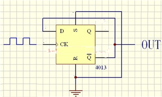
    You need to design a frequency divider circuit to help achieve this.

    For example, the below is 1/2 frequency divider, so you can use Q to sync one IC and NQ to another to provide 180-deg phase shift.

  • Thanks Hong. This didn't really answer my question. I wasn't asking how to do the phase shift. There are many possibilities for doing this. I was asking how to configure the Master UC2526A device and subsequent Slave UC2526A devices for synchonisation with the slavves phase shifted relative to the Master device.

    In the datasheet on page 6 it highlights how to synchronise a master to multiple slaves to the same clock phase, 

    "Multiple devices can be synchronized together by programming one master unit for the desired frequency, and then sharing its sawtooth and clock waveforms with the slave units. All CT terminals are connected to the CT pin of the master and all SYNC terminals are likewise connected to the SYNC pin of the master. Slave RT terminals are left open or connected to VREF. Slave RD terminal may be either left open or grounded."

    If you want the slaves to be synchronised but phase shifted, would the approach be highlighting from the datasheet to connect all CT terminals. The Master with RT and CT generates the clock from its Sync pin. Then if this clock is used to produce an identical but phase shifted clock to input to the Sync pin of the Slave device would this work?

  • Hi,

    I cannot find any info how to make phase shift from master to slave. The datasheet only shows all slave to sync to the same master. So to make phase shift an external phase shift signal is needed

  • Thanks Hong. Noted. You are correct in regards to what is stated in the datasheet with syncing many slaves to the same master. I agree that to add phase shift, an external phase shift circuit is required.

    Also to provide further context is that we are using the UC2526A in open-loop at maximum 50% duty cycle by effectively disabling the error amplifier, and therefore effectively the pwm latch during normal operation. The pwm latch is still active for cycle by cycle current limit.

    Therefore my understanding is that because we are not running in closed loop with pwm, for syncing the same master to multiple slaves we only need to connect all sync pins of the UC2526A devices together. We don't need to tie the CT terminals together. Correct me if I'm wrong here.

    In regards to phase shifting the slaves to the master there I can see a couple of ways:

    1. Have timing RT, CT on the master. The master then generates a clock on its sync pin(pin 12). A phase shifter circuit then takes this master clock and generates the phase shifted clcoks for the slave UC2526A devices. Each phase connects to the respective sync pin of the respective slave uc2526a device. Because open-loop and no pwm is required (operating at 50% duty-cycle) we don't need to connect all CT pins together.

    2. RT, CT timing as per 1. But drive sync with a clock frequency 10% higher than the free-running frequency (as set by RT, CT). The sync clock is then passed to the external phase shifter to generate the slave UC2526A clock phases as mentioned in method 1. Because open-loop and no pwm is required (operating at 50% duty-cycle) we don't need to connect all CT pins together.

    Please indicate if there are any problems with either of methods 1 or 2.

    Thanks.

  • Hi,

    Therefore my understanding is that because we are not running in closed loop with pwm, for syncing the same master to multiple slaves we only need to connect all sync pins of the UC2526A devices together. We don't need to tie the CT terminals together. Correct me if I'm wrong here.

    [Hong] Show your circuit how you want to connect - I am not able to follow your words - a circuit can be much better than these words to show how you want to connect.

    1. show your circuit you intend to do

    2. Show your circuit you intend to do.