This thread has been locked.

If you have a related question, please click the "Ask a related question" button in the top right corner. The newly created question will be automatically linked to this question.

BQ25756: only buck mode

Part Number: BQ25756
Other Parts Discussed in Thread: BQ25820

Tool/software:

Dear Team,

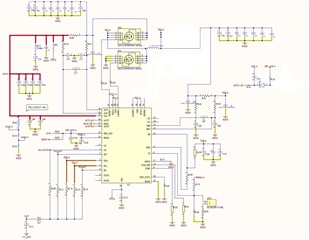
I am using BQ25756 IC for BMS application, and we want only use buck mode then what we have to do, please help me.

running we facing no charging current issue in buck mode ( we remove BTST2 voltage only )

  • Hello egindi,

    Thanks for working with this. I recommend using the BQ25820 if you want to use buck-only mode. The BQ25820 is pin-to-pin with the BQ25756. The BQ25820 has a mode pin that is used to set the inductance.

    Let me know if you have any questions about this and let me know if you think the BQ25820 will work for your application.

    Best Regards,
    Ethan Galloway

  • OK , In buck-boost we also facing no charging current. CE pin low 

    All configuration according to DEMO board else STAT1 & STAT2 are floating

  • Hello engindi,

    I've got a few questions to help debug this:

    • What's the input/output voltage and what's the charge current?
    • Can you send me the register file?
    • What do the status and flag registers report?

    Best Regards,
    Ethan Galloway

  • now all thing good but at low voltage in boost mode there are some humming issue , how can is resolve it

    vin=15

    boost volt= 28v

  • Second thing , can we play 4 BQ circuit in parallel mode. 

    When i used in this parallel mode a looping current occur.

  • Hello engindi,

    Got it. I'm glad to hear the board is working.

    I've got a few questions to debug the remaining issues.

    1. What frequency is the humming at? Is it a high pitched hum or a low pitched hum?

    2. How were the 4 BQ25756 ICs arranged in the circuit?

    Best Regards,
    Ethan Galloway

  • Hi Ethan,

    Sorry for delay,

    We ordered as you suggested on Buck mode IC BQ25820.

    Till we get that IC, we are working on BQ25756, and we are close to completing this project.

    Now we are facing a problem that is looping current. I am sharing with you a picture which is the conclusion of my overall circuit.

    When we charge battery in boost mode a looping current flows through this diode and this diode circuit is necessary to discharge battery at high rate in discharging mode, how can I prevent my circuit from this looping current (this type of 4 channels works in parallel mode).

  • Hello Engindi,

    No problem. Let me know if the BQ25820 works for your project.

    For the diode, I have a few suggestions:

    Can you disable the BQ device when the power supply's power fails?

    Can you use the BQ25820's power path or auto reverse mode instead of a diode? This should allow the input supply's current and the system load current to be separated. The BQ25820 won't oscillate in this configuration.

    Also, keep in mind that voltage from the battery can flow through the high-side FET's body diode and into the input power supply because the BQ25820 only has 2 FETs.

    Let me know if either of those solutions will work for your system.

    Best Regards,
    Ethan Galloway

  • Can i stop Bi-directional feature in BQ25756, If yes than How?

    I only required Power supply to battery charger 

  • Hello Engindi,

    Can you elaborate more on what you mean by this?

    The bidirectional feature is enabled by enabling reverse mode with the I2C command EN_REV=1. The bidirectional mode of the BQ25756 won't activate unless it's activated by I2C.

    Did you find an alternative or workaround for the diode in your circuit to stop the looping current?

    Best Regards,
    Ethan Galloway

  •  yes , we are written program like this it is only working in Buck mode so CE pin low only when power supply voltage higher than battery voltage so in this case there is no looping current flow , 

    i think Pin 32 is to use Enable and disable Reverse mode via hardware.

  • Hello Engindi,

    Got it. Thanks for the update.

    Reverse mode will only turn-on if you enable it via I2C commands.

    Pin 32 (VAC) is the power input to the IC.

    Best Regards,
    Ethan Galloway

  • Hi,

    I got BQ25820 IC,

    I inserted it in the module of BQ25756 and I found that after 8V the IC wakes up and the O/p voltage keeps on increasing with respect to the input voltage and remains constant at 24 volts until the input voltage becomes 27 volts then 28v input and output voltage is 25, then 28v until the input voltage becomes 30 volts

    But when we connect the battery from battery side, after that connect the power supply at 29V, the power supply suddenly reflects 52V and charging does not start,

    What we have to see.

  • Hello Engindi,

    I've got a few questions to help debug this:

    • Can you send me your updated schematic?
    • Can you send me a register file if possible?
    • What are you using the for the battery?

    Best Regards,
    Ethan Galloway

  • Hi,

    • The updated schematic is same as per the guide of BQ25820 schematic, we put this IC in BQ25756 module which we already brought, we removed some mosfet (boost mosfet) and put the input common source mosfets, SYS mosfets, 0E along with the required short resistor same as in BQ25820 user guide.
    • We are using LiFePO4 cell battery whose nominal voltage is around 24V.

    Another thing when we give supply from input side without any battery connected, STAT1 and STAT2 LEDs blinking alternately. 

    Register files i will provide you soon , 

  • Hello Engindi,

    As Ethan mentioned, Can you please provide your register file?

    What is the input voltage?

    What is battery voltage?

    Please provide schematic, I understand it should be the same, but there might be something important that was skipped over.

    Best Regards,

    Christian.

  • Hi,

    We have 2 board.

    1. BQ25756 module in which we have change all thing according to BQ25820 so you can understand there is nothing to change schematic. ( all components placed as per BQ25820 Module user guide )

    2. We make a PCB according to BQ25756 and now we change it according to BQ25820 ( optional components not placed in this PCB ) , I am sharing with you updated Schematic according to BQ25820

    We found same scenario in both PCB ( Module and our PCB)

    Input voltage is 29V 

    Battery voltage is 26V

    Updated schematic 

    It is look like BQ25820 Boost Battery voltage and flash it on Input side.

    There is nothing changed in Resistor file (software side) all value are in by default setting , only hardware thing we changed.

    I will share you register file as soon as possible.

  • Please find attached file.

    RED mark we removed.

    BLUE mark we placed.

    R9, R1005 , R1003 we placed 0E which are in bottom side.

    R32 -18K at the place of 0E. 

    R12 0E and D1 15V zener in bottom side.

  • Hello engindi,

    I understand nothing was changed in the software, but the BQ25820 also has status registers that could indicate what the issue is. Please send register information.

    Best Regards,

    Christian.