Other Parts Discussed in Thread: TPS25751,
Tool/software:
Hi I'm working with a TPS26750 system, trying to follow along with AN slvafl1 "TPS25751 and TPS26750 EEPROM Update Over I2C". Could you help me confirm how my system architecture should be configured so that my external host mcu can update the eeprom and do the initial eeprom programming ?
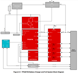
In the TPS26750 ds, fig 8-1 shows the system block diagram with the eeprom connected only to the TPS i2cc bus, and the external host mcu i2c_master is connected to TPS i2ct (ie there is no direction connection from external host mcu i2c to the eeprom). Is that connection scheme all that is required to let the external mcu write to the eeprom ? So that would mean that the FLrd, FLad, FLwd, etc commands are driven from the external host mcu on the host_mcu_i2c_master to TPS_i2ct bus, and then the TPS bridges its i2ct to i2cc busses to allow the external host mcu to access the eeprom ?
But in the TPS26750 EVM, from the schematic in the EVM UG slvucp8 in fig 5-10, it looks like the Tiva host mcu is connected to both the TPS i2cc and i2ct. So that would mean the Tiva mcu is directly connected to the eeprom i2c. Is that required for either initial eeprom programming or updating an image that is already present on the EEPROM ? If so then does i2c traffic from the Tiva mcu on the i2cc bus to the eeprom interfere with the TPS since then there would technically be two masters on i2cc ? In that case would you need to hold the TPS in reset ? If so then how? Or are you supposed to mux eeprom i2c to either TPS i2cc OR ext_mcu_i2c_master ?
In summary, is the fig 8-1 system arch from the TPS ds correct and complete or do I have to follow the EVM schematic which has a material difference ? Please help thanks. -Steve