Tool/software:
Hi Team,
any suggestion or modification for this schematic? thanks for your help and learn from you,
This thread has been locked.
If you have a related question, please click the "Ask a related question" button in the top right corner. The newly created question will be automatically linked to this question.
Tool/software:
Hi Team,
any suggestion or modification for this schematic? thanks for your help and learn from you,
I would modify the resistor values:
R5=0Ω, R121=250Ω, R120=350Ω
As it stands, the circuit will hit max Vout trying to reach 13.7V.
What's the purpose of R5? Is it a discrete resistor or modeling something else?
I'm assuming you want VOUT = 3.0V
The ratio between R121 and R120 can be calculated per the datasheet:
And it needs to be scaled such it draws above the minimum output current:
R121=250Ω & R120=350Ω will give you give you feedback to 3.0Vout while pulling the minimum 5mA.
Best,
Gregory Thompson
reposting answer because I made too many assumptions the first time
Hi Sir,
ok~got it, but we see in the datasheet that typical value of the reference voltage is 1.25v, per the schematic and formula, so as figure below:
R2 correspond to R120, R1 correspond to R121, is right?
if R5 modify 0 ohm, so R120 should be 250 ohm, R121 should be 250 ohm, right?
thanks for you help and learn from you.
Hi Tommy,
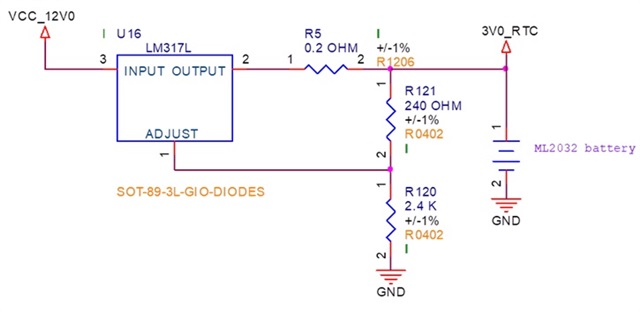
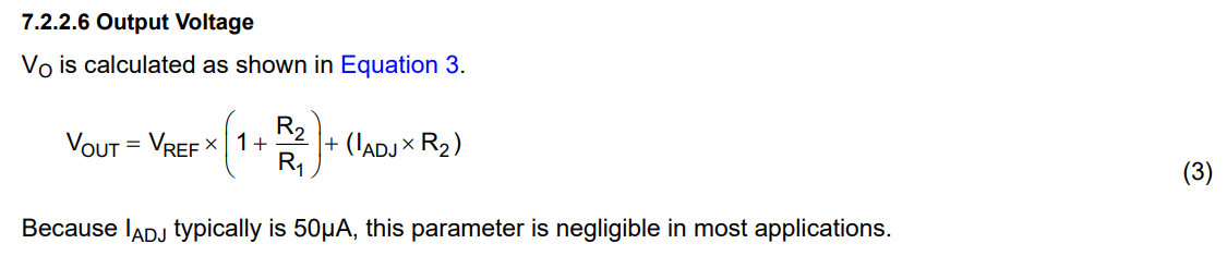
That is correct, R2 maps to R120 and R1 maps to R121. Making both 250Ω would give you an output voltage of 2.5V, which would work if that is desired. I had assumed you wanted 3.0V volts so I sized them as R121=250Ω & R120=350Ω.
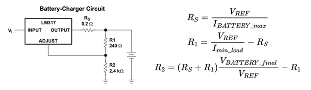
Just to clarify: R5 would be nonzero if you want to limit current to below a specific value. Some applications require this, but a value of R5=0.2Ω is somewhat useless on the LM317L because it would hit the LM317L's own internal current limit before any additional protection. Here are the formulas for that if you are looking for a specific current limit:
Best,
Gregory Thompson