Other Parts Discussed in Thread: TPS65987, , TPS65988DK, TPS65988
Tool/software:
Hi AE,
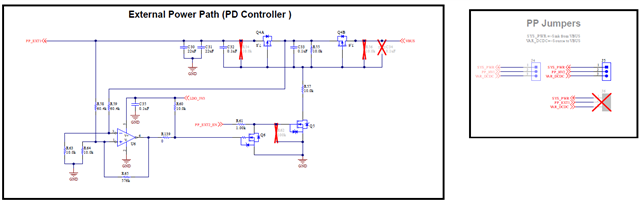
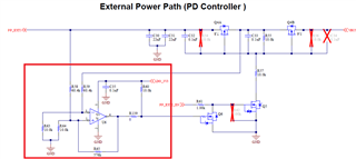
We are planning to design a related circuit and would like to ask if the TPS65987 can support external source power supply?
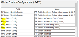
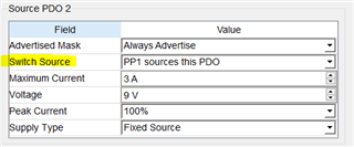
Additionally, if it is supported, could you provide relevant circuit diagrams and firmware settings for reference?
Best Regards