This thread has been locked.

If you have a related question, please click the "Ask a related question" button in the top right corner. The newly created question will be automatically linked to this question.

TPS61094: Using with Lithium-Ion SuperCapacitors

Part Number: TPS61094
Other Parts Discussed in Thread: TLV6713

Tool/software:

There is a new generation of supercaps (Lithium Ion based) and I would like to know if we could use these instead of regular super capacitors with TPS61094?

One example is this:

LIC1030Q3R8107 (datasheet)
100F
0.6A rated current and 5A absolute max.


TPS61094 SuperCap settings:

Ichg at 100mA
Vchg at 2.5V

TPS61094 primary power 3 x 1.5V alkaline cells.

Use case: nB-IoT. Load, 300mA max peak, 10uA standby, 20mA nominal

  • Hi Anupam,

    It looks fine to me. But I'm not the expert of the super capacitor. So I recommend reaching out to the CDA to see if our charging profile are acceptable for their super capacitors.

    Best Regards,

    Travis

  • Hi Travis,

    There is one detail that may be critical. 

    This datasheet says

    Minimum rated voltage: 2.5V

    Further, it says:
    "To avoid short-circuit, after usage or test, Lithium Ion capacitor needs to discharge to >2.5V (Not lower than 2.5V)"

    So I guess this acts more like a battery from a safety perspective. While with TPS61094, we can set a Vchg of say 3.5V DC, but  VSUP_UVLO is typically 0.85 V, which is way below the minimum requirement for the Li-Ion Supercap.

    So I guess, this is a no-go?

    Regards,
    Anupam

  • Hi Anupam,

    You can apply external supercap voltage detection circuit to shut down the IC if you have a MCU on your system. Or you can apply an resistor divider to divide SUP voltage and connect to EN pin. So the EN will become low if the SUP drops below the threshold. But note that our EN logic accuracy might not be satisfying.

    Best Regards,

    Travis

  • Do you mean using this kind of chip? Or do you have a more specific reference from TI I could use?

    In the former case, the charging of the chip comes from VIN directly and not from TPS61094 buck part anymore, so we are loosing the nice MPPT feature of the auto buck/boost and burning energy into the charging resistor.

    If using SUP pin itself to toggle EN, then I don't see how this could work. If you use a voltage divider here, you are draining the capacitor all the time, so even with EN set to low (as you said, it's not a variable threshold anyway), the voltage across the capacitor will fall below the 2.5V threshold. The EN pin range is too large (between 0.2V to 0.6V it is in undetermined state), so it means that if it disable at 2.7V, the divider must "generate" 0.2V there, and thus, will still be undetermined at 5.4V too since it'll generate 0.4V.

    I've looked at TLV6713 chip too, and if I understand correctly, it should work better here if I understand it correctly. The idea would be to have a very low current voltage divider (since the chip only requires 1nA in its sense pin), we can go as low as 10nA in the voltage divider, (270MOhm for 2.7V). The chip itself draws 11µA which is a bit high (maybe it's acceptable for the OP?). Do you know a better, equivalent comparator circuit that using less quiescent current?

    Also, there's the issue with exiting from this state. Since EN is low when the voltage of the capacitor is below the threshold, even when VIN resume, it'll still be disconnected and not charge the capacitor anymore. Technically, it's dead.

    I wonder if instead of toggling EN pin, one should toggle MODE pin instead (FORCE BUCK MODE), so when VIN resumes, the supercapacitor is charged first (so it should cross the threshold again) and resume the chip to AUTO BUCK BOOST. However the load must then deal with VIN voltage (it's ok if there's a LDO or a DC/DC on the load to regulate itself while the capacitor is charging, but not if you don't have this).

    Or if you can't use the force buck mode, use a Schottky diode from VIN to the input of the TLV6713 comparator (on the low part of the voltage divider), so it again can cross the threshold and toggle the EN pin back to high when VIN is present. 

    The issue in that case is the reserve leakage current in the diode that's, typically around 50nA for a Vreverse of ~2.5V that happens when VIN is 0V, which means that the voltage at the sense input will be 0V unless the divider starts to generate more than 50nA, so it adds to the loss and lower the efficiency. So to have a working threshold here, the divider should have at least 4µA of current in it, (510kOhm/100kOhm) so that's a lot to be wasted again.

    In the former case, you're wasting ~13µA (11µA from TLV + 300nA from TLS + pull up current) drained from the capacitor.

    In the latter case, you're wasting ~17µA (11µA from TLV + 4nA from TLS + pull current + 4µA in the divider bridge), drained from the capacitor.

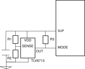
  • A bit like this in fact:

    With, for VCap threshold set to 2.7V, R1 = 230MOhm, R2 = 40MOhm, R3 = 800KOhm. In that example, when VCap decays below 2.7V, typically because VIN is missing, OUT is forced low, MODE is ~0.2V, TPS61094 goes in forced buck mode (that is, the input is plugged to the output waiting for the VIN voltage to cross the UVLO threshold). When VIN reaches ~1.8V, the capacitor starts to charge via the buck mode, and its voltage will increase. When it reaches 2.7V, the TLV6713 toggles the MODE output back to high, and the TLS61094 will resume its auto buck/boost mode. The VOUT of the TLS61094 will thus look like VIN until the capacitor is charged more than 2.7V and will restart to look as expected when it does. Notice that the TLS61094 is not shutdown when VCap < 2.7V, so it's still drawing ~300nA on the capacitor. The output is still connected to the input, so if you don't have a way to disable the output when the voltage is too low, it'll still draw from the input (but not the capacitor). Compared to the TLV circuit drop (in the tens of µA range), it's negligible.

    Please confirm my understanding is correct. I've also found TLV4041R2 which works the same but I think it's a bit better (lower quiescent current, no pull up resistor, thus more efficient overall).

  • Hello Anupam,

    I'm not the expert for TLV6713 and  TLV4041R2. So please submit another thread for recommendation on these parts.

    About TPS61094:

    You are correct on the block diagram. Force buck mode is a better solution. But note that 094 is a buck charger that only supports step down operation at buck mode. So the sup will only be charged when Vout (bypassed from Vin) over VSUP.

    Best Regards,

    Travis