Other Parts Discussed in Thread: TPS2378, , LM76002, LM76005
Tool/software:
Hello TI Forum Team,
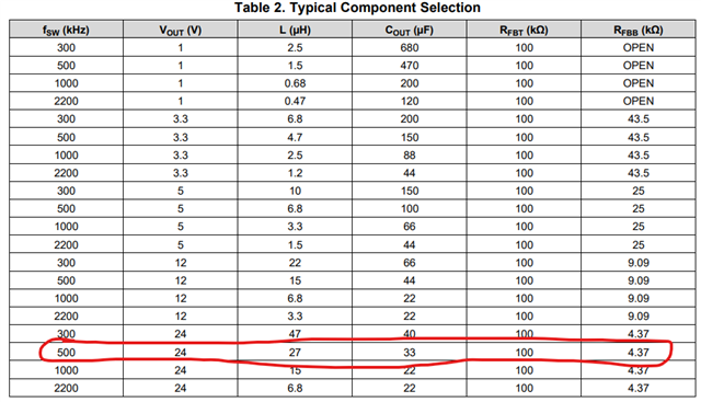
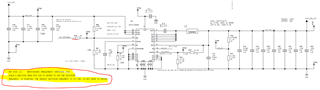
I have created a schematic of LM76003RNPR Schematic with below design requirement.
Vin Range: 44V to 50V
Vout: 24V @ 2A
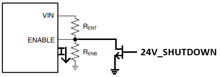
1. The signal 24V_SHUTDOWN is coming from TPS2378 PD Controller via CDB pin using MOSFET logic implementation. I have kept the 80.6K resistor connected to this pin as well. Do I need this resistor or not?
2. For Pgood Pin, I have used the voltage divider by using output voltage to proivde the voltage to pgood pin to track the o/p.
It would be highly appreciable if you could review the design. I have some points to highlight.