This thread has been locked.

If you have a related question, please click the "Ask a related question" button in the top right corner. The newly created question will be automatically linked to this question.

TPS25833-Q1: Efficiency issue

Part Number: TPS25833-Q1

Tool/software:

Hi 

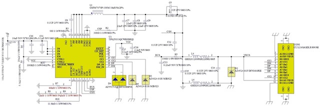
Below is my customer's schematics, it is now switchinng at 300KHz. 

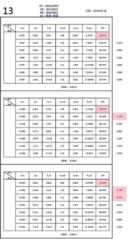
From the datasheet efficiency curve, for 300KHz, 3A output, it shows greater than 90% efficiency.

However for 300KHz 3A output, my customer can only get 87% efficiency, my customer's schematics and test result as below, can you help review if any thing we can do to improve the efficiency?


  • Hi PYTsai,

    Here are a few comments:

    1. The DCR of L3 looks good but it's value is too high for the beads (L4/5), try to use FBs with lower DC resistance.

    2. In the PCB layout, make VIN, VOUT and ground bus connections as wide as possible. This reduces any voltage drops on the input or output paths of the converter and maximizes efficiency.

    3. Check the ESR of C6 and make it's value as small as possible.

    4. For all other caps. please use candidates with lower ESR if possible (priority lower than C6).

    5. Double check how the input socket is mount on the board. Sometimes a bad soldering on socket through hole pins can increase loss.

    BR,

    Ke Wang

  • Hi Ke

    can you help review customer's layout attached below, if there is any concern?

    2705.TPS25833_USB_PCB Layout .pdf

  • Hi PYTsai,

    The layout looks good on the loop impedance. I don't see any significant issue impacting the efficiency. Use 2 oz copper rather than 1 oz may help the efficiency if you are focusing on the PCB design to improve the efficiency.

    BR,
    Ke Wang