This thread has been locked.

If you have a related question, please click the "Ask a related question" button in the top right corner. The newly created question will be automatically linked to this question.

TPS546A24A: TPS546A24A power noise question

Part Number: TPS546A24A
Other Parts Discussed in Thread: TPS546B24A,

Tool/software:

Dears

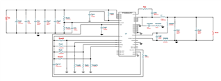
We got an issue that is power noise, currently we design TPS546A24A/TPS546B24A in our product.

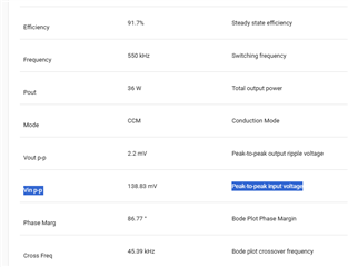
Before we design them, we already simulated by using TI Webbench and the result is also good.

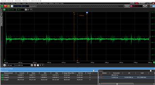
Also, TI FAE(Taiwan) did measurementt in the past, the report is pass. It measns that the design is OK basedon the result.

But, according to customer’s feedback, they found some cards worked abnormally recently, cannot connect to it.

They tried to measured signal and found Vpp is even up to 1V on the GPIO which is reset signal.

Due to the signal is reference to Vcc 12V power plane, they doubt it is related to power noise.

Please advise.

Thanks.

  • Hi Jack,

    Please check the PCB layout and grounding. Although the design passed simulations, the actual PCB layout and grounding can introduce noise issues. Make sure to use proper ground planes, maintain short return paths, and minimize loop areas for both power and signal traces. Verify that decoupling capacitors are placed close to the power pins. You might also consider adding ferrite beads or small-value resistors to the signal lines to suppress noise.

    Additionally, ensure that the affected GPIO has appropriate pull-up or pull-down resistors. If it's floating, it may pick up noise.

    If the reset signal runs parallel to high-speed or high-current traces, it could induce noise. Consider routing sensitive signals away from switching nodes or using ground planes for shielding.

    Thank you,
    Tomoya

  • Dear Tomoya

    Thanks for the reply immediately.

    Basically, we know what you provide suggestion.

    In this case, if need to add additional components, do you mean it should design input side?

    The reset GPIO has PU resistor and its routing didn't close to high speed trace.

    Thanks.

  • Hi Jack,

    Tomoya will respond to this in a few days.

    Thanks,

    Calan

  • Hi Jack,

    In this case, if need to add additional components, do you mean it should design input side?

    Yes, that's correct. The goal is to attenuate the high-frequency noise generated by the buck converter and prevent it from propagating back into the power supply line. Here is a useful application note you can refer to for filtering input noise. First, you can experiment with different input capacitors that provide a low impedance path to ground for the specific noise frequency you are trying to address. If that doesn’t resolve the issue, consider adding a series ferrite bead or an input LC filter.

    https://www.ti.com/lit/an/slyt782/slyt782.pdf

    Thank you,
    Tomoya

  • Dear Tomoya

    Thanks for the reply.

    The circuit is good concept, also we can try do verify it whether it can resolve our current issu.

    However, it will cause PCB evolution. Currently, is there a possible way that we can set register value to solve it?

    Please advise.

    Thanks.

  • Hi Jack,

    Are you referring to the PMBus register value for a potential software fix? If so, one option you could try is adjusting the VDD5 setting in the (B5h) USER_DATA_05 (POWER_STAGE_CONFIG) Register. The default voltage is 4.7V. Lowering the VDD5 voltage level to 4.5V, 4.3V, or even 4.1V can decrease the gate driver strength and slow down the MOSFET switching transitions. 

    Thank you,
    Tomoya