Tool/software:
Hi!
I'm using two TPS929160 on a new board to drive 32 LEDs (1 per channel). The LEDs have a nominal forward voltage of 3,1V @ 120mA but I don't need to use them at their full power, 100mA would be OK!
Everything seems to be working just fine, I imported and adapted the EVM code to work on a PIC18F and I can run the different patterns that are on the original EVM code.
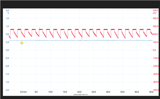
But I'm having a problem with the maximum driven current. The maximum I had until now was around 20mA per channel.
Even if I drive only one LED that is the maximum I get. The LED attached to ERR pin keeps turned off everytime (but it works, I've seen it in the past).
I already tried using different voltages (12V and 5V) on Vsupply and Vbat, nothing different besides heat dissipation.
I changed the FSx configuration and got the same result.
I'm using R(ref) = 6K32 and getting V(ref) = 1,235V. VLDO is 5V.
Do you have other ideas that I may look for?
I'm leaving in attach a piece of code that I am using and that is basically imported from the EVM code.
Thanks in advance for your attention.
BR
// Calculate and store the CRC of data from 0x00 to 0xFF
crcInitial();
// When CAN is not used, the read offset is always 0. When CAN is used, it depends on the number of transmitted bytes.
if(CAN_USED == FALSE) {
read_offset = 0;
}
// Unlock device
clearLockAll(BROADCAST);
// Clear POR, FAULT for device
setClr(BROADCAST, CLRFAULT | CLRPOR);
// Check if ACKEN is set
for(dev_idx = 0; dev_idx < DEVICE_CNT; dev_idx++) {
FlexRead(device_address[dev_idx], FLEXWIRE0, DATA_LENGTH__1, TRUE);
if(ledRcvBuffer[read_offset] & ACKEN_1) {
ackEnabled[device_address[dev_idx]] = TRUE;
}
else {
ackEnabled[device_address[dev_idx]] = FALSE;
}
}
// ***Disable all channels for device - this is reset value of register, but ensure for restart of program
disableAllCh(BROADCAST);
// Set PWMFREQ = 2000Hz
// Can set PWM frequency as broadcast which will overwrite all other settings in same register
setPWMfreq(BROADCAST, PWMFREQ__2K0);
// Need to set REFRANGE per device to retain existing setting - PWM frequency and REFRANGE are for TPS92912x in the same register
// Set REFRANGE = 512
for(dev_idx = 0; dev_idx < DEVICE_CNT; dev_idx++) {
setRefRange(device_address[dev_idx], REFRANGE__512);
}
//***Set DC for all Channels - actually this is the reset value in EEPROM
regValue[0] = IOUT__MAX;
setIOUTAllCh(BROADCAST, ®Value[0], TRUE);
//***Set PWMOUT for all Channels - PWM high is reset value in EEPROM and PWM low is reset from register
regValue[0] = PWM__1;
setPWMAllCh(BROADCAST, ®Value[0], TRUE);
setPWMhighAllCh(BROADCAST, ®Value[0], TRUE);
// Set Single-LED-Short threshold and Low Supply Threshold - Settings are for EVMs
setSLSth(BROADCAST, SLSTH0__2V50, 0);
setSLSth(BROADCAST, SLSTH1__2V50, 1);
// Need to set SLSEN and LowSupplyTh per device to retain existing setting - REFRANGE is for TPS929160/240 in the same register
for(dev_idx = 0; dev_idx < DEVICE_CNT; dev_idx++) {
setLowSupplyTh(device_address[dev_idx], LOWSUPTH__4V);
enableSLS(device_address[dev_idx]);
}
// Clear FAULT for device because low supply threshold was just set
setClr(BROADCAST, CLRFAULT);
// Enable diagnostics for all channels - actually this is the reset value in EEPROM
enableDiagAllCh(BROADCAST);
//Assign LED Drivers to the correct LED according to the model and color of the LEDs
if(model == MODEL_REAR)
{
blinker_dev_idx = LED_DRIVER_1_IDX;
otherFunc_dev_idx = LED_DRIVER_2_IDX;
blinker_limit = BLINKER_NLED_REAR-1;
}
else //if MODEL_HEAD
{
blinker_dev_idx = LED_DRIVER_2_IDX;
otherFunc_dev_idx = LED_DRIVER_1_IDX;
blinker_limit = BLINKER_NLED_HEAD-1;
}
//Turn off all LEDs
enableAllCh(device_address[blinker_dev_idx]);
for(ch_idx = 15; ch_idx >= 0; ch_idx--)
{
regValue[0] = PWM__0;
setPWMoneCh(device_address[blinker_dev_idx], regValue, device_LED_idx[ch_idx]);
}
//Enabling one LED only
regValue[0] = PWM__1;
setPWMoneCh(device_address[blinker_dev_idx], regValue, 8);