This thread has been locked.

If you have a related question, please click the "Ask a related question" button in the top right corner. The newly created question will be automatically linked to this question.

LM34966-Q1: PSpice for TI error

Part Number: LM34966-Q1

Tool/software:

Dear Team,

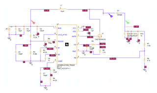
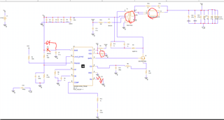
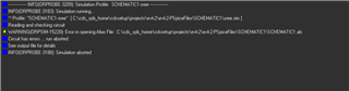
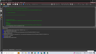
I have been working on a simulation using the LM34966QPWPRQ1 IC, and when I try to run the simulation, I encounter an error. Could you kindly assist me with this issue?

Looking forward to your response.


  • Hello Sreehari,

    Thanks for using the e2e forum.

    The error message says "Circuit has errors.. run aborted"
    Based on this I cannot tell the issue.

    Could you check the following:
    - Did you run the PSpice model directly after download without modification to see if the default testbench simulates fine?
    If this is the case, we can rule out any version or software issues.

    - Afterwards, can you show me the schematic, or provide the model files you are trying to simulate?
    With this we can start debugging the circuit.

    Thanks and best regards,
    Niklas

  • Hi Niklas,
    I am trying to simulate the circuit I referred to from the EVK board. I have attached the file for your reference.

    EVK.DSN

  • Hi Sreehari,

    Thanks for attaching the file.
    In this design, the power stage is missing and regulation pins like COMP, CS and FB are floating.
    I am afraid the simulation cannot work properly like this.

    I attached the default testbench model for LM34966. Can you try to open this file and run a simulation with this model?

    LM34966-Q1_PSPICE_TRANS.zip

    Thanks and best regards,
    Niklas

  • Hi Niklas,
    My kind apologies for the file I sent earlier. Here is the correct fileEVK2.DSN.

  • Hi Sreehari,

    Thanks for the update and your patience.
    As you have two model thread open in parallel, I will merge them here for a better overview and answer both of them.

    Regarding your first schematic from the other thread:
    - The diode model you used was not within the PSpice for TI library. I exchanged it with a ideal diode model and the simulation was running fine

    As this was a pure boost topology, you will not see clean switching behavior if both VIN and VOUT are set to 24V, so I recommend to reduce VIN a bit so the device is actually boosting.
    I would also recommend to reduce the SS capacitance, as this slows down the startup immensely, leading to long simulation times.
    To get to a steady state faster, you can simulate with SS cap of 1nF or 10nF. (This may lead to an overshoot of Vout at the beginning, but you safe some waiting time)

    Regarding your new flyback schematic from this thread:
    There are still some errors in the schematic which cannot work.
    - FB is connected to a cap to GND. This is the output voltage reference and need to be connected to AUX or VOUT.
    - The transformer and diode model are not included in the model library as well. You can either use ideal diode model and ideal inductors with coupling (funciton is called "K_linear"), or you import external models into the libraries, which limits the probe count to three probes)
    A tutorial on this can be found in this video

    - Some additional design comments:
    - VCC cap of 1nF is very small. This is the supply for the driver.
    - Compensation need to be check for a stably regulation loop. Please use the calculations given in the datasheet, or use one of our calculation tools.
    - D2 diode might be placed in the wrong direction

    If you need further assistance, please let me know.

    Best regards,
    Niklas