This thread has been locked.

If you have a related question, please click the "Ask a related question" button in the top right corner. The newly created question will be automatically linked to this question.

TPS1H200A-Q1: Latch-off protection function confirmation

Part Number: TPS1H200A-Q1

Tool/software:

Hi team,

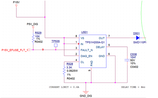
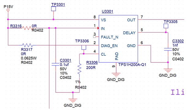
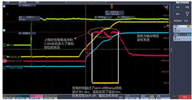
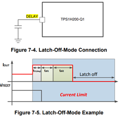
When we applied the TPS1H200A-Q1 high-side switch chip, we encountered the problem of triggering latch-off when powered on. We need to confirm with you:

1. The logic of fault diagnosis when powered on?

2. When we tried to set the current limit to 10A, we found that it could not be reached. The actual maximum was less than 3A. So I would like to ask, what is the maximum value of the current limit threshold that can be set?

3. I also want to confirm the timing method after the current reaches the current limit. If the current drops below the current limit halfway and then reaches the current limit again, will the timing be restarted?

Thank you for your support!

BR,

Ethan

  • Hi Ethan,

    1. Are the DIAG_EN and FAULT pins pulled high? If DIAG_EN is high, then faults will be reported. The voltage on the FAULT should be high if there is no fault and low when there is a fault. You can also refer to the Table 7-2. Fault Truth Table in the datasheet for specific cases.

    2. That is because of the internal current limit; you cannot set the external limit to 10A. The external current limit has to be less than the internal current limit or else the internal limit will take over. 

    3. What does your DELAY pin configuration look like? What exactly do you mean by "if the current drops below the current limit halfway"? 

    Thanks,

    Rishika Patel 

  • Hi Rishika,

    Thank you for your reply. I will add some information.

    When we configured the chip as follows (configuration 1), the problem of false triggering of latch-off protection occurred during power-on. ① The 15V of the front stage can be established normally, and the startup time is 15ms; ② The rear stage OUT is established and stops after about 3.4ms;

    Configuration 1 is:

    1. The VS pin/IN pin/DIAG_EN pin are short-circuited together and connected to the 15V input

    2. The FAULT pin is pulled up by an external 5V. This 5V power supply is established relatively slowly, so the FAULT pin may be in a floating state for a period of time during the power-on process

    3. The CL pin is pulled down by a 3.3K resistor, and the current limit is configured to 0.6A

    4. The Delay capacitor is designed to be 10nF, and the Delay time is designed to be 4ms

    The chip was subsequently configured in another way (Configuration 2)
    Configuration 2 is:
    1. The VS pin and DIAG_EN pin are shorted together, connected to the 15V input, the IN pin is pulled up by 5V, and the FAULT pin is left floating
    2. The CL pin is pulled down by a 200Ω resistor, and the current limit is configured to 10A
    3. The Delay capacitor is designed to be 1nF, and the Delay time is designed to be a maximum of 1.3ms

    The following two problems occurred during the power-on process of configuration 2:
    1. The designed current limit is 10A, but the actual measured maximum is only 2.6A, which is less than the internal current limit range (3.5A, 6A)
    2. The charging time of the power-on capacitor exceeds the designed delay time of 1.3ms of the 1nF capacitor, but the output is not turned off

    The question in the previous email [I want to confirm the timing method after the current reaches the current limit. If the current drops below the current limit midway and then reaches the current limit again] is to confirm:
    After the charging current reaches the current limit, it drops and then reaches the current limit again, similar to the waveform in the yellow circle area in the above figure, will the latch-off delay time be recalculated? If it is recalculated,
    it can explain the phenomenon that the charging time exceeds the latch-off delay time, but the output is not turned off.

    Please help me take a look again, thank you~

    BR,

    Ethan

  • Hi Ethan,

    The external current limit cannot be set to 10A as the internal current limit maximum is 6A. 

    If the overcurrent condition is removed before the delay time ends (tdl1 + tdl2), the delay time should reset because the current is not holding at that max value and instead is decreasing in your waveform. Please see below.

    What is on the load? What is the type of load and are you using an e-load during this test? If so, is it in constant resistance or constant current mode?

    Thanks,

    Rishika Patel