This thread has been locked.

If you have a related question, please click the "Ask a related question" button in the top right corner. The newly created question will be automatically linked to this question.

UCC256404: Input current oscillations when controller changed to UCC256404 (add controller heating)

Part Number: UCC256404
Other Parts Discussed in Thread: PMP21683, , UCC256302, UCC256402

Tool/software:

We are updating the controller (UCC 25630x to UCC256404) on a TI LLC reference design (PMP21683) and are following the TI migration paper (SLUA 996A). While the power supply regulated nicely, we are noticing two major problems:

1.  The controller runs much hotter and hits the thermal fault limit once the input supply goes above 395 V(works fine at 380) - we assume that this is because the switching frequency increases, but did not happen with the previous controller.

2. The input current changes by about 10-15 mA (4-6 Watts) every second or so. For example, it is 700 mA for ~350 ms, then 710 mA for 650 ms, and the cycle continues. The output is rock solid and no burst mode. This would not be such a big problem in general, but we are doing efficiency measurements and this change is throwing us off. We are also noticing a slight "jump" (2-300 mV) in the gate drive voltage of the lower Mosfet that happens at the same time with the current variation. 

Has anyone seen any of these problems (especially the second one)? Is there some sort of protective feature that triggers this?  Is there a fix to this?


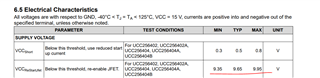
For reference, below are the values that were changed from the previous design. The schematic is here: https://www.ti.com/lit/pdf/tidrzl6

Part      old    new

R138   127k   41k 
R137   68.1    42 
R136   412     270
R110   51.1k  40k
R112   10 k    8k 

  • Hi,

    1.  The controller runs much hotter and hits the thermal fault limit once the input supply goes above 395 V(works fine at 380) - we assume that this is because the switching frequency increases, but did not happen with the previous controller.

    The RVCC in 40x is 13V whereas in 30x RVCC is 12V. That would increase gate drive losses. Currently I dont see any resistance in series with the turn off diode in the schematic. So, could you increase gate turn off resistance (in series with turn off diode) so that some of the power loss will be dissipated across the resistor. Also, you can connect a pull-down PNP transistor from source to gnd. This would also help reducing the power dissipation inside the controller.

    2. The input current changes by about 10-15 mA (4-6 Watts) every second or so. For example, it is 700 mA for ~350 ms, then 710 mA for 650 ms, and the cycle continues. The output is rock solid and no burst mode. This would not be such a big problem in general, but we are doing efficiency measurements and this change is throwing us off. We are also noticing a slight "jump" (2-300 mV) in the gate drive voltage of the lower Mosfet that happens at the same time with the current variation. 

    How does the VCC waveform looks like when this happen? Could you share the ISNS, VCR, HS, Vout (AC coupling) waveforms?

    Regards

    Manikanta P

  • We discovered more: the reason for the heating and the oscillation is that the controller periodically re-starts the start up process from the HV pin, although Vcc is already available, stable and so is RVCC (RVCC is between 13.06-13.15V). So it kind of resets itself (the internal JFET turns back ON), restarts from VIN (which pulls quite a bit of current for about 300 ms, then runs on VCC for about 600ms and resets again. Not sure what puts it in this mode, could you please help with some suggestions (could not find in the datasheet what would restart the process)

  • Hi,

    The HV startup will only be reenabled when VCC goes below VCCRestartJFET threshold.

    Could you confirm if this is the case?

    Regards

    Manikanta P

  • The VCC is stable at 18.3V

  • Could you let me know how is the connection of HV startup? Is it connected to AC input or DC input?

    Regards

    Manikanta P

  • The PMP21683 design uses UCc256302 which doesnt have x-cap discharge function whereas UCC256404 has the x-cap discharge. If you connect the HV startup to DC input incase of UCC256404, x-cap discharge will get activated that would lead to increase in temperature. You need to use UCC256402 instead of UCC256404.

    Regards

    Manikanta P

  • I am not sure I follow the x-cap discharge issue. How is its absence of the discharge cap turning ON the JFET?

  • The way x-cap discharge works is the controller will keep looking for zero crossing (this would occur in case HV is connected to AC input) at the HV pin. If that doesn't detect any zero crossing, then it's going to activate the x-cap discharge. Since you connected the HV pin to the DC input, the zero crossing will never occur.

    Regards

    Manikanta P