This thread has been locked.

If you have a related question, please click the "Ask a related question" button in the top right corner. The newly created question will be automatically linked to this question.

LM5118: Webench design for 9V is not working when the PCB of same design is fabricated and populated

Part Number: LM5118
Other Parts Discussed in Thread: CSD13202Q2

Tool/software:

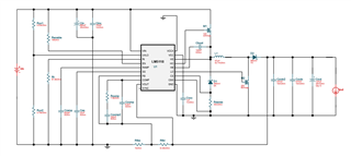
I have used TI Webench Power designer for design help of generating 9V @1A using a 3.7V battery and LM5118MH/NOPB Regulator. When we tested the PCB, The IC (LM5118MH/NOPB) is getting 3.7V VIN, enable pin is getting 3.7V but output of 9V is not being generated. We have tried removing IC and re soldering the same LM5118MH/NOPB. At last Output is coming "0". This is an urgent requirement. This is the schematic used

  • Hi Ejaz,

    the LM5118 can operate down to 3V once started but need for the startup at least 5V.

    Please check if the operation starts if it is supplied by > 5V.

    Best regards,

     Stefan

  • Hello stefan,

    There was a small mistake in my PCB. I have corrected that mistake and tested the board now. Initially I started raising the voltage from 3.7V by 0.1V, when the supply voltage reached 4.4V the output of 9V is achieved without any Load. I didn't even provide 5V to start Controller. 

    Now, my design requirement is generating 9V@1A for 3-4.2V Input range. 

    It is contradicting both webench design and datasheet. Please give your insights on this.

  • Hi Ejaz,

    The requirement for the controller is to start operation at at least 5V or lower. So it can be that the device starts already at 4.4V.

    For a operation start at 5V we also have to consider temperature and device variances. So the start of the operation will properly start already at lower voltages.

    Best regards,

     Stefan

  • Hello Stefan,

    Thanks for the reply.

    In that case, the device shall work once it is operated in 4.4 - 5V for few seconds and then switch back to 3.7V.

    When I started supplying from DC regulated power supply, I have provided 5V input and then after 10-15 seconds I started reducing towards 3.7V. The Output Voltage gradually getting dropped when I am decreasing from 4.4 to 3.7V. 

    This shouldn't happen right ?

    Regards

    Ejaz.

  • Hi Ejaz,

    please check the used MOSFETs if this are getting into full conduction mode when the supply is below 4.4V.

    What is the Miller Plateau of the used MSOFETs?

    Best regards,

     Stefan

  • Hi stefan,

    The Mosfet used is same for both M1&M2 which is CSD13202Q2. The Miller Plateau of this Mosfet is 1.5V approximately.

    Regards,

    Ejaz

  • Hi Ejaz,

    good this the MSOFET should be working fine under this condition.

    Can you please provide some scope plots of: (showing each a few ms and a few switching cycles (5-10)

    - HS / HO / LO / HB

    - VIN / VOUT

    - COMP / SS / VCC

    You can also try to supply VCCX with an external supply e.g. 5V and check if this changes the behavior. This would give some more indication for the root cause.

    Best regards,

     Stefan