


Tool/software:
Howdy,
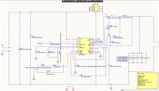
I've recently used the webench design tool to create a schematic for a 48V to 5V buck converter at a nominal current of 15A, to power 2 5A Pis, a 250mA laser diode, and additional other devices. The voltage source will be a 48V lithium based battery with a battery management system, and in the final design the single 5V buck converter will be used in conjunction with other buck converters of different output voltage. The webench generated the design, 7 LM5190RGYR 33V-52V to 5.00V @ 17A, with EMI filter option enabled. The following is the generated design and the schematic that I replicated for this design. Some substitutes are marked. Is it possible to review this schematic and additional questions I have?
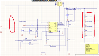
On the left I have not created a capacitor bank for Cin. I am not sure how to create one or what guidelines to follow, especially because 1uOhm of ESR is incredibly difficult if not impossible to achieve, the 8.891A IRMS is difficult as well, and the designer asks for a very specific value of 437.155 uF (which tolerance might be unable to meet regardless?). If you have any guidelines for this, I'd appreciate it.
On the right I put 5 Couts in series, since it says the quantity is 5 on the webench schematic. Are the capacitors supposed to be in parallel or in series? What would be the point of putting the capacitors in series, if so?
Also, for the signal ground, should it be renamed as something other than GND? I am not very familiar with ECAD (Altium) software and whether or not I should make this distinction.
As for component selection, there are 3 substitutes, which should be upgrades or direct substitutes; everything in the BOM is in volume production and 1 is in NRND (Cboot).
If you can help with this type of inquiry, thank you for your consideration. If you need any other information do tell me.
Thank you for your time,
Yoav Binyamin,
Texas A&M University

