This thread has been locked.

If you have a related question, please click the "Ask a related question" button in the top right corner. The newly created question will be automatically linked to this question.

UCC25660: VCCP and start-up problem

Part Number: UCC25660

Tool/software:

Hello, 

I’m designing a 120W 48V LLC converter using the UCC256601 chip, the input voltage is 380V to 400V with nominal voltage of 390V, I´m supplying the 390V using a rectifier board

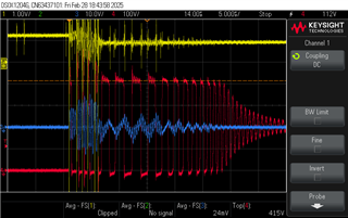
The problem I have is the circuit does not start normal operation, and when I checked VCCP it was triangular waveform, and according to the datasheet VCCP should be more than 14V(VCCStartSelf) for the IC to start switching.

Also there are periodic pulses(about 1 second apart) on LO pin, which indicates some type of fault condition according to the datasheet.

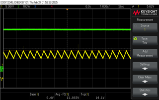
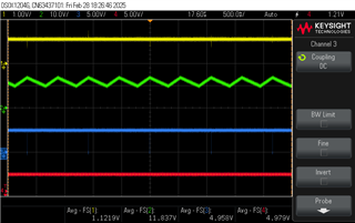
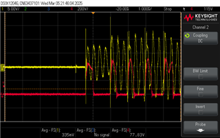
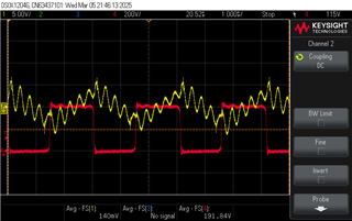
Green trace is VIN 390V, yellow trace is VCCP

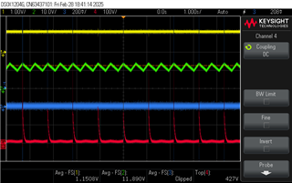
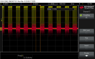
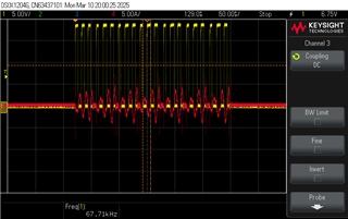
Green trace is VCCP, yellow trace is BLK pin, blue trace is LO pin

Here is the schematic of the LLC circuit

Can you please help me to figure out the problem in my circuit?

  • Hi,

    Could you share the waveform for the TSET and V5P pin during startup?  Could you also share the zoom in waveform of the ISNS,HS, Vout during startup and before going going into fault state.

    Also, share the design calculator with me.

    Also, could you make few modifications to the schematic? 

    1. Connect the anti Parallel diode to the gate as shown in the EVM schematic

    2. Connect 10k in series with opto

    3. Can you change the cap values of C24 and C16 to 330p.

    Regards

    Manikanta P

  • Hi Manikanta,
    thank you for your help, I tried the modifications in 1,2 and 3, but I still have the same results.
    also the system does not startup and then go to fault state, it stays trying to start as I can see from the pulses on LO pin.

    the following is the TSET, V5P, ISNS and HS, waveforms before any modifications in the circuit:

    yellow = BLK, green = VCCP, blue = TSET, red = V5P


    yellow = BLK, green = VCCP, blue = ISNS, red = HS

    and zooming on HS

    yellow = BLK, blue = ISNS, red = HS

    zooming more on HS

    yellow = BLK, blue = ISNS, red = HS

    this is the design calculator
     UCC25660x_Design_Calculator_Rev1.xlsx
    I hope these will be helpful,
    and thanks again

  • Hi Ramy,

    Could you reduce the ISNS value below 100ohm? I see lots of ringing on the ISNS. Could you use tip and barrel method while measuring this signal (How to Measure Ripple and Transient in Power Supplies | CUI Inc)

    Regards

    Manikanta P

  • Hi Manikanta,

    before changing the sense resistor I measured ISNS using the paperclip method since it's not possible to use the barrel method, but the ringing still there.

    yellow = ISNS, red = HS

    zoomed in

    after that I changed the sense resistor with 50Ohm one, and now the switching started but not continuous even at full load

    yellow = HS, red = primary current

    zoomed in

    and this is Vout
      

    yellow = HS, red = primary current, green = Vout (AC coupling)

    zoomed in 

    I tested also with 100Ohm sense resistor and the circuit is switching with the same behavior as the 50Ohm one, and also tested with 220Ohm sense resistor but the circuit is not switching anymore, back to the original issue.

    I put the circuit in the original state (original components values) as before the modifications you suggested in the first reply, and it is still switching, actually the previous screenshots are taken with the original component values, so I think we can assume that the issue is the current sense circuit.

    in conclusion the circuit is switching now, but I don't know why the switching is interrupted, also by using low value for sense resistor I lose OCP, do you have an idea how to solve this?
       

  • Hi,

    Controller is operating in the burst mode. You can tune the LL pin settings to make it work in the normal switching.

    Regards

    Manikanta P