This thread has been locked.

If you have a related question, please click the "Ask a related question" button in the top right corner. The newly created question will be automatically linked to this question.

LM2577: LM2577T/ADJ/NOPB Circuit seems to fail after simple repeated use. Need Advice

Part Number: LM2577

Tool/software:

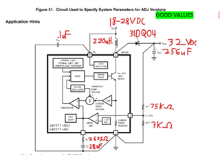
Hello! I have been working with this chip and with the design attached.

After having failures on a breadboard this circuit is now on a solder board for better connection.

It was working from 12/11/2024 until attempting to use it on 1/17/2025 when the circuit started smoking which caused damage to some capacitors, wires, and shorted the positive and ground rails of the board.

After checking and replacing all damaged parts and soldering the circuit together the chip now appears to be broken as the output voltage is now the same as the input voltage unlike the boosted behavior it did before.

This is the 3rd chip to fail even when the working circuit design is used. 

Can someone help me understand where I could be going wrong and if there is possibly a better less fragile chip to achieve the results of the circuit shown above?

  • Hello Thomas,

    Thanks for using the e2e forum.
    If I understand correctly, the device is working fine on first startup, but after operating the device over a longer timespan, it eventually breaks. Is this correct?

    If damage only occurs after a certain amount of time, it is often related to temperature increase.
    The LM2577 device should not have a overtemperature protection, so if it heats up more and more, it can eventually destroy itself.

    Can you give me the load conditions for this application?

    LM2577 is a rather old device that is not used in many applications anymore, so I have no reference with similar failures like this.
    We do have never devices, which come with strongly improved protection features to avoid such behavior.
    The best fit for this should be LM5157 or LM5158. (Depending on the maximum load conditions)

    Best regards,
    Niklas

  • Niklas,

    This circuit only has a load of 0.5A.

    This circuit is meant to power some op amps with a load current of ~1A at 32VDC  

    Looking at the datasheet this should be within the spec of the chip.

    Just to clarify the failure was not after a long time of constant usage. The chip was never in use for more than an hour at a time. It was also the first activation of the chip after many weeks that the failure occurred.

  • Hi Thomas,

    Thanks for the update and the clarification.
    I agree the operation conditions are within spec.
    The external components selected look okay to me as well.

    Right now I cannot say what the root cause is.
    Can you confirm there were no possible ESD hazards when storing and retrieving the boards?
    Can you also give more details and what is broken at the IC after the damage occurred? E.g. are some pin internally shorted, or is it just not turning on again?

    Thanks and best regards,
    Niklas

  • Niklas,

    There were no ESD hazards present during failure.

    The electrical board was isolated from any possible other conductor or hazard during the test.

    After repairing the circuit (New parts, wires, new solder) the input voltage and the output voltage of the circuit remains the same.

  • Hi Thomas,

    Thanks for the feedback.
    So if VOUT equals VIN after turn-on, the device is simply not operating, but there is no short of the input voltage correct?
    Would it be possible to do waveform measurements at SW, FB and COMP pin voltage on the damaged IC?

    This might give additional insights why the IC is not working anymore.
    Can you also specify which components were broken aside from the IC?
    E.g. just the diode or also the capacitors?

    Thanks and best regards,
    Niklas