This thread has been locked.

If you have a related question, please click the "Ask a related question" button in the top right corner. The newly created question will be automatically linked to this question.

TPS551892-Q1: Request for TPS551892-Q1 schematic review

Part Number: TPS551892-Q1

Tool/software:

Hi, TI expert

The customer requested a schematic review using TPS551892-Q1.

[spec]

- Input : 3.2Vdc ~ 4.15V

- Output : 3V , 3A

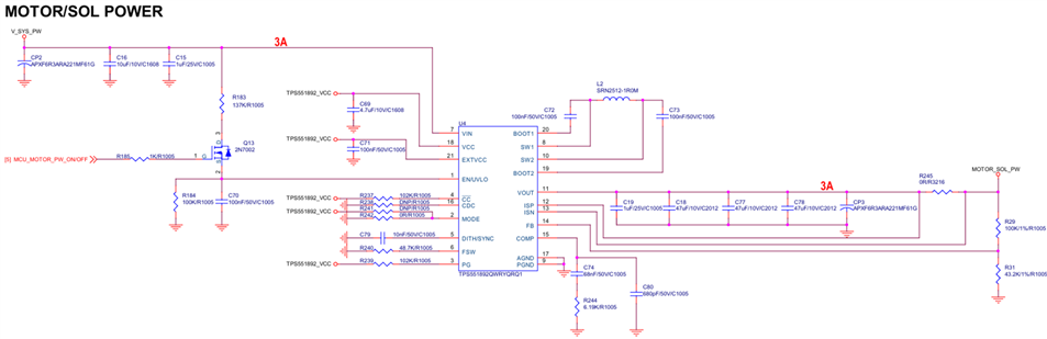
Are there any problems with the circuit? Are there any areas that need to be modified? Please review.

Thank you.

  • Hi Grady,

    Thank you for reaching out. May I know what is the application and customer here?

    Below is my feedback:

    1. If the MCU_MOTOR_PW_ON/OFF signal is higher than 1.23V, customer can directly use this signal to enable EN pin. Just add a 100kohm pull down resistor.

    2.Change C69 to 16V rated to ensure 2uF effective capacitance with DC derating.

    3.Change L2 to 4.7uH with 8A Isat.

    4.Recommend to reserve RC snubber in SW1 and SW2.

    5.If customer doesn't use the output current limit function, remove R245 and directly connect ISN and ISP to Vout.

    6.Can you provide part number of output caps for me to check loop parameters?

    7.Follow layout guideline.

    Regards,

    Mulin

  • Hi, Mulin

    Thank you for review.

     The client is undisclosed and the application is Breast Pump.

    The application is not automotive, and we proposed TPS552892RYQR and TPS551892QWRYQRQ1 to meet the customer's required specifications, but TPS551892QWRYQRQ1 was selected because it was cheaper.

    Thank you.

  • Hi, Mulin

    I have modified the circuit based on the customer's comments.

    1. If the MCU_MOTOR_PW_ON/OFF signal is higher than 1.23V, customer can directly use this signal to enable EN pin. Just add a 100kohm pull down resistor.

    → Since the MCU output voltage is 3V, delete the existing circuit and connect the MCU directly.

    2.Change C69 to 16V rated to ensure 2uF effective capacitance with DC derating.

    → C69: 4.7uF voltage change from 10V to 16V

    3.Change L2 to 4.7uH with 8A Isat.

    → 4.7uH/rated 5.9A/Isat 8.2A, SRP5030CA-4R7M change

    4.Recommend to reserve RC snubber in SW1 and SW2.

    → Add RC snubber circuit

    5.If customer doesn't use the output current limit function, remove R245 and directly connect ISN and ISP to Vout.

    → Short after deleting R245

    Please review the modified circuit attached.

    2705.Schematics.pdf

    Thank you.

  • Hi Grady,

    Recommend to change R247 and R248 to 1206/0805 package.

    Can you provide part number of output caps for me to check loop parameters?

  • Hi Grady,

    We have not seen an update from you for some time, so I assume the issue is solved.
    I close this thread now. If there is still something open, please reply and the thread will get opened again.
    If you have any other question or of the thread has been locked, please open a new one.
    Clicking the Resolved Button also helps us to maintain this forum.

    Regards,

    Mulin

  • Hi, Mulin

    Our reply was delayed due to the customer's delay in responding.

    Mulin sadi) Can you provide part number of output caps for me to check loop parameters?

    → CP3: APXF6R3ARA221MF61G (6.3V / 220uF)
         C19,C18,C77,C78: It is said that the part number is not fixed. (Only the value on the circuit)

    Thank you.

  • Hi Grady,

    Thank you for your feedback. Recommended compensation parameters: R244=10k, C74=15nF, C80=100pF.

    Regards,

    Mulin