This thread has been locked.

If you have a related question, please click the "Ask a related question" button in the top right corner. The newly created question will be automatically linked to this question.

TPS26750: Patch bundle size and boot details

Part Number: TPS26750
Other Parts Discussed in Thread: TPS25751

Tool/software:

Hi I've got a few questions about loading the TPS26750 from eeprom and i2c to help with my system boot process:  

1. Does it say anywhere what the size of the patch bundle is that gets written to the eeprom ? The ds says the eeprom needs to be at least 36 kbyes so that implies the patch bundle must be a little under 144 kbits ? 

2. Is there any benefit to using a larger eeprom or a possibility of storing a 3rd or 4th patch bundle ? Like is there a way to tell the TPS to load from a different RegionStart addr and offset ? 

3. If I were going to load the patch bundle to the TPS from my external host mcu over i2ct instead of eeprom, then is the size of that patch bundle the same ~144 kbits ? 

4. Is the time it takes for the TPS to load the patch bundle roughly the same from the eeprom over i2cc as from the host mcu i2ct (maybe little under half a second at 400k i2c) ? 

5. Once the TPS successfully loads the patch bundle from the eeprom and transitions to APP mode, then is there any way for my external host mcu to asynchronously force the TPS to transition back to PTCH mode and wait for a new bundle to be sent from the external host mcu over i2ct ? In the rm there is a command 'GO2P' that sounds like this function but it also says that only works with the NegotiateHighVoltage boot mode. In my system I will probably want to use SafeMode and I can think of a few different TPS configs I might want to use depending on my end product state. 

6. Referring to AN SLVAFL1 TPS25751 and TPS26750 EEPROM Update Over I2C: there must be a flow chart that exists that shows what the TPS boot process looks like, because section 2.1 reads like someone looking at that flow chart and describing it over five paragraphs of prose. Is the source boot process flow chart available anywhere to review? Almost seems like there is a logical inconsistency how it says if there is a crc error while reading the low region then it doesn't read the high region (what does it do then?), but if there is a crc error reading the high region then it tries to read the low region. And also it can repeat attempting to read the different regions but not clear how that works. Would be easier to understand if there were just a flow chart. 

Thanks, Steve 

  • Hi Steve, 

    Thank you for reaching out!

    I will get back to you on the questions above by Wednesday. 

    Best Regards, 

    Aya Khedr 

  • Hi Steve,

    1. Does it say anywhere what the size of the patch bundle is that gets written to the eeprom ? The ds says the eeprom needs to be at least 36 kbyes so that implies the patch bundle must be a little under 144 kbits ? 

    The patch bundle is the size of the low region binary image generated from the GUI, refer to response for Q3. 

    2. Is there any benefit to using a larger eeprom or a possibility of storing a 3rd or 4th patch bundle ? Like is there a way to tell the TPS to load from a different RegionStart addr and offset ? 

    TPS26750 only checks for the header in the 1st (low region) and 2nd (high region) patch bundle. Any additional bundles after that are not checked for. 

    3. If I were going to load the patch bundle to the TPS from my external host mcu over i2ct instead of eeprom, then is the size of that patch bundle the same ~144 kbits ? 

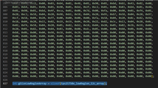
    At the end of the lowregion binary you can find the sizeof() function to report the size of the low region binary used for PBMx (PBMs). 

    4. Is the time it takes for the TPS to load the patch bundle roughly the same from the eeprom over i2cc as from the host mcu i2ct (maybe little under half a second at 400k i2c) ? 

    EEPROM loading may take less time since the PD will automatically read and load from the EEPROM upon boot-up.

    5. Once the TPS successfully loads the patch bundle from the eeprom and transitions to APP mode, then is there any way for my external host mcu to asynchronously force the TPS to transition back to PTCH mode and wait for a new bundle to be sent from the external host mcu over i2ct ? In the rm there is a command 'GO2P' that sounds like this function but it also says that only works with the NegotiateHighVoltage boot mode. In my system I will probably want to use SafeMode and I can think of a few different TPS configs I might want to use depending on my end product state. 

    What's the purpose for loading a brand new configuration into the PD? If you're looking to change register configuration I would recommend just reading/writing to the PD registers instead of loading another configuration. If you need to change the entire configuration during operation, it may be best to use PBMx (Host loading via i2C) instead for better flexibility. 

    6. Referring to AN SLVAFL1 TPS25751 and TPS26750 EEPROM Update Over I2C: there must be a flow chart that exists that shows what the TPS boot process looks like, because section 2.1 reads like someone looking at that flow chart and describing it over five paragraphs of prose. Is the source boot process flow chart available anywhere to review? Almost seems like there is a logical inconsistency how it says if there is a crc error while reading the low region then it doesn't read the high region (what does it do then?), but if there is a crc error reading the high region then it tries to read the low region. And also it can repeat attempting to read the different regions but not clear how that works. Would be easier to understand if there were just a flow chart. 

    Can you point to the figure(s) that you need more clarification on?

    Thanks and Regards,

    Raymond Lin